VM-7 System Manual
Chapter 2 Description of the System
12
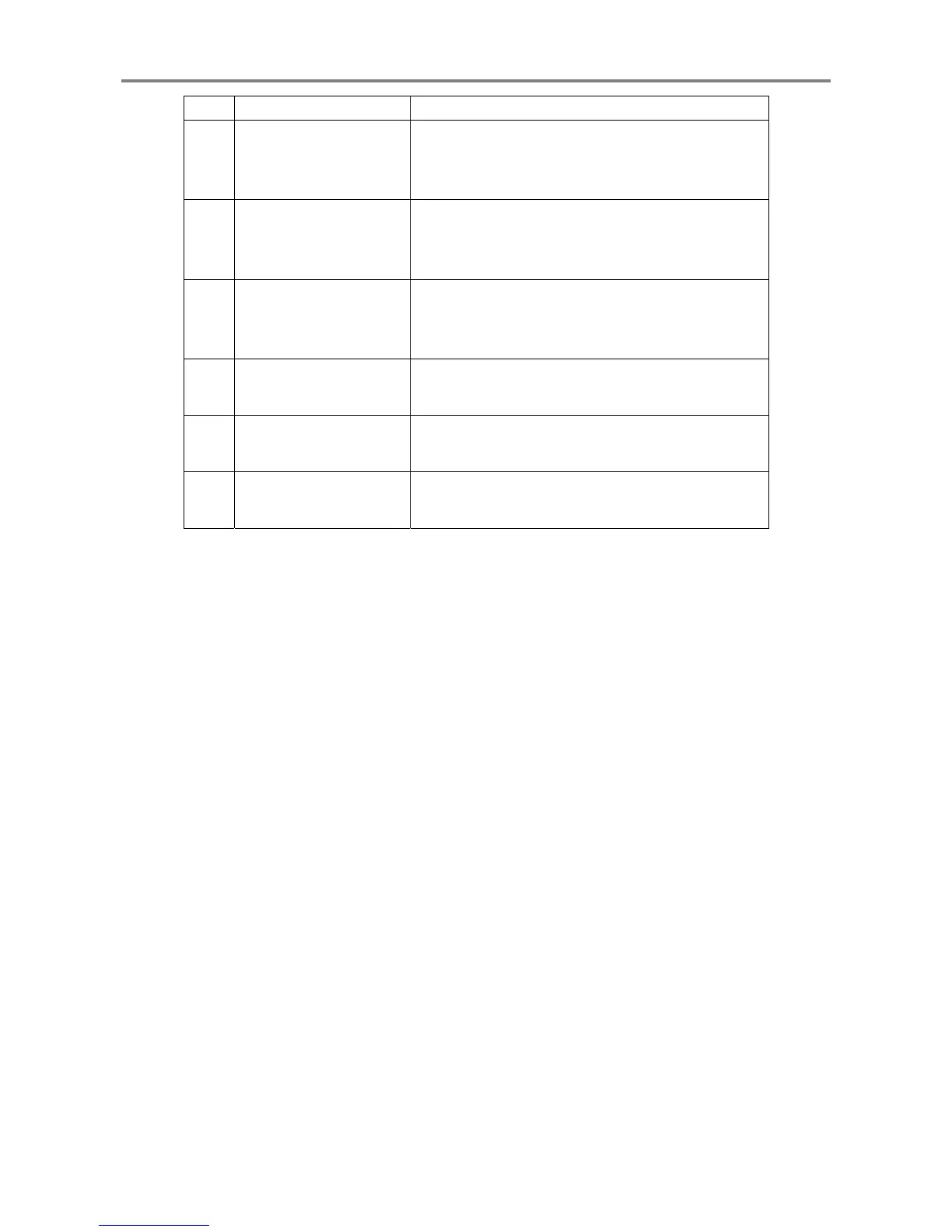
No. Name Function
⑨
Analysis Module
communication
connector
Outputs data processed by the Analysis Module.
⑩
Network communication
connector 1
The measurement value and status of each monitor is
transmitted to the network via the Network
Communication Module installed on the Slot 1.
⑪
Network communication
connector 2
The measurement value and status of each monitor is
transmitted to the network via the Network
Communication Module installed on the Slot 2.
⑫
Local communication
connector
Communicates with the PC in which MCL View and
FIELD CONFIG are installed.
⑬
Contact output terminal
block
Outputs contact signals according to the logic related
to each module warning.
⑭
Power Supply Module
terminal block
Supplies power and provides POWER-OK contact
output.
 Loading...