VM-702 ABSOLUTE VIBRATION
MONITOR MODULE
Page 1 of 4
VM-7 SERIES
SPECIFICATIONS
30902E1.3
Issued Feb. 2009
Revised Mar. 2010
Non-incendive *
1
Custom set up Tropical spec. I/O terminal block for:
1
Class I Division 2 CSA
1 VM-761 instrument rack
2 VM-762 instrument rack
*1 In future
VIBRATION MONITORING
Accuracy : ±2% of F.S. at 25°C *
3
±3% of F.S. at 0°C to 65°C
*
3
Recommend monitoring range
: 100 to 1000µm
HPF : 10Hz to 100Hz (-3dB), field changeable.
*
4
(4
th
-order / 10
th
-order)
LPF : 200Hz to 1kHz (-3dB), field changeable.
*
4
(4
th
-order)
Note) *3 At calibrate frequency.
*4 There is un-match combination.
Sequence function : Used to prevent alarm output that is caused by excessive
vibration during machine startup. Block off the
DANGER/ALERT alarm, or switch the alarm setup value to
another number magnified by setup number.
Sequence Setup : Block off
1 to 10 (1 step, field changeable)
Suppression function : If the vibration value is less than the setup value,
this function is forced to suppress the measured vibration
value and recorder output.
*5 Suppression Setup Value: 0 to 5%
( 0.1% step, field changeable)
ENVIRONMENTAL CONDITION
Operating temperature : 0 to +65°C
Storage temperature : -30 to +85°C
Relative humidity : 20 to 95%RH (noncondensing)
Power Consumption
Module : Less than 15W
MATERIAL AND FINISH
Face plate : ABS (Black)
Sheet : Polyester tough top (Gray)
Base plate : Alminium alloy (Silver)
MASS
Body : Max. 1.0kg (2.2lb)
INPUT
Input system : Max. 2 systems
Input system Channel combination : A: 1ch, 2ch B: 3ch, 4ch
Input impedance : Approx. 50kΩ
INPUT TRANSDUCER
1ch : VK-202A or FK-202F
2ch : CV-86 or CV-88
3ch : VK-202A or FK-202F
4ch : CV-86 or CV-88
OUTPUT
Indicators : OK LED (Green)
Monitor output : Location : Front panel and rear panel
1 or 3ch : BUFF
*
2
2 or 4ch : BUFF, SEIS, ABS can be selected.*
2
Output impedance : 100Ω
Output current : Max 0.5mA
Recorder output : Voltage or current output proportional monitor range.
(REL, SEIS can be selected on 1 or 3ch
*
2
)
(SEIS, ABS can be selected on 2 or 4ch
*
2
)
Output range : 1 to 5VDC, 4 to 20mADC
0 to 5VDC, 0 to 10VDC
I/O conversion accuracy : ±3% of F.S. at 25°C
*
3
±5% of F.S. at 0°C to 65°C *
3
Max. load resistance : 600Ω (current mode)
Output impedance : Approx. 500Ω (voltage mode)
Insulation resistance : 10MΩ at 100VAC
Burnout function : Downscale 0%
Downscale 0mA / 0mV
Transducer power supply : Proximity transducer : -24VDC/25mA Max.
Piezoelectric transducer : +24VDC/4mA
(constant current)
Alarm contact : Number of relay : 6 points (logic changeable)
Contact type : Dry contact (SPDT)
Contact capacity : 250VAC / 5A, 30VDC / 5A
Note)
*2 BUFF : (Buffer Signal)
Input signal from a transducer is output via buffer amplifier.
REL : (Relative vibration)
SEIS : (seismic vibration)
The signal is converted from velocity signal to displacement signal.
(787mV/ 100µm)
ABS : (absolute vibration)
The signal is subtracted SEIS (seismic vibration) on 2 or 4ch from
the input signal on 1 or 3ch (Relative vibration).
(787mV/ 100µm)
*3 at calibrate frequency.
LARM
Alarm set point : 2 points (DANGER, ALERT), from 0 to 100% of
monitor range, field changeable
Alarm set accuracy : ± (0.2% of F.S. +1digit) or less at 25°C
Alarm set repeatability : ±1digit or less at 25°C
Alarm delay time : 0.5, 1 to 99sec, (1 sec step, field changeable)
Alarm reset : AUTO-RESET or SELF-HOLD field changeable.
Alarm contact mode : Normally de-energized / Normally energized
Alarm bypass function : Block off alarm output (DANGER)
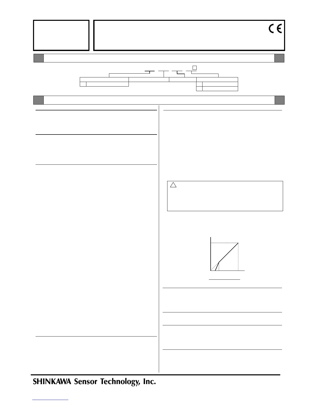
0 100(%)
Input
100(%)
OUTPUT
DISPLAY
0
*5
Input / Output characteristic
5
VM-702 /NB1 /CSU /TRP /TB
Model Code / Additional Spec. Code ( )
No entry if additional
spec, code is not specified.
! WARNING
In case the SEQ. magnification number is setup from 2 to 10, the
alarm setup value magnified by setup number while the SEQ.
circuit is in progress should stay at or lower than 110% of the
maximum monitor range. If the number is more than 110% of the
monitor range the alarm may not output.
Specification
 Loading...