SBG 00185 Copyright 2015 14
Quick-Start Guide for PRSalpha and PRSstandard tools
Secon 2. Running a Part File
This secon covers setup procedures performed prior to previewing or running the part le.
Zeroing the Z axis
The Z axis must be zeroed each me that the machine is turned on or bits are changed. Zeroing can
be done to either the top of the material or to the table surface.
Zeroing to the top of the material is a beer choice when a
precise cut depth is needed (when cung an inlay pocket, for
example).
Zeroing to the table surface is a beer choice when through-
cung parts in wood. Because wood products naturally vary in
thickness, the top surface of any given area may be higher or
lower than other areas. Zeroing to the table surface will pro-
vide the most consistent through-cung results.
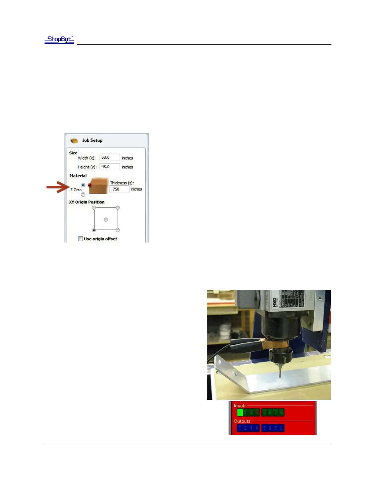
Whichever locaon is chosen, the locaon must be idened
in the CAD/CAM program (as shown here for VCarve Pro). Fail-
ure to match what is specied in the soware with what is
done at the table can result in ruined material and/or broken
bits!
Z axis zeroing process
Ensure that the soware is set to Move/Cut mode.
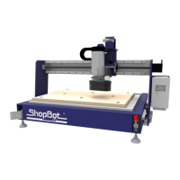
Place the grounding clip on the bit, if possible. Other-
wise, place it on the collet nut or sha of the spindle.
Set the plate down directly beneath the bit.
NOTE: To test the circuit before running the zeroing
roune, touch the plate to the boom of the bit. Check
that input 1 lights up on the screen and goes o as soon
as contact is broken.
Click on the Z zero buon, or type a C2 command. The Z
axis will touch the plate twice and then move up to a
safe height. The Z axis is now calibrated and the ma-
chine is ready to cut.
Place the Z zero plate back in its holster. Remove the grounding
clip from the bit and secure it safely.