SBG 00185 Copyright 2015 23
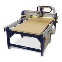
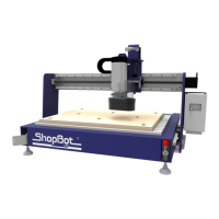
Quick-Start Guide for PRSalpha and PRSstandard tools
Number of utes: The number of utes on a bit is essenal to calculang proper feed and speed
rates. For most applicaons, a bit with 1, 2, or 3 utes can be used, but feed rates and RPMs must be
adjusted to maintain proper chip load (see below).
End shape: Straight and up-spiral bits come in a variety of end shapes. Square ends are most common,
and are a good choice for creang pockets and grooves, cung proles, simple leering, and drilling
operaons. Ball (or rounded) ends are best for 3D carving. VCarve bits are oen used to create com-
plex leers for sign making. They can also be used to chamfer edges and create countersinks for screw
holes.
Calculang Feed Rates and RPMs with Chip Load:
Chip load refers to the actual thickness of the chip cut by each revoluon of the cuer. It is the meas-
urement that all feed rates and speed calculaons are based on.
A spinning bit generates fricon and heat as it moves through the material. Part of this heat is pulled
away by the ying chips. A larger chip load pulls away more heat, but also puts more stress on the
cuer. Each material has its own ideal chip load range that balances heat dissipaon with cuer stress.
A basic chart (in .pdf format) for common materials can be found in the SB3 soware by clicking on “[T]
ools”, “Chip [L]oad Calculator”, and “Chip Load Help”. Use this chart along with the Chip Load Calcula-
tor to determine a good starng speed for each toolpath.
Do not rely on the tool database default sengs when calculang feeds and speeds for a toolpath.
Those values are only placeholders and are not intended for any parcular material.