Shure Incorporated
20/55
1.
2.
3.
4.
1.
2.
Microphone Status LED Behavior / Color
Channel identify: Light ring segment
Firmware update in progress Green (ring fills up, turns off, repeats)
Reset
Network reset: Red (rotates around ring)
Factory reset: Blue (rotates around ring)
Error Red (split, alternate flashing)
Device power-up Blue (rotates around ring)
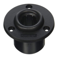
Installing the Cable-Exit Plug
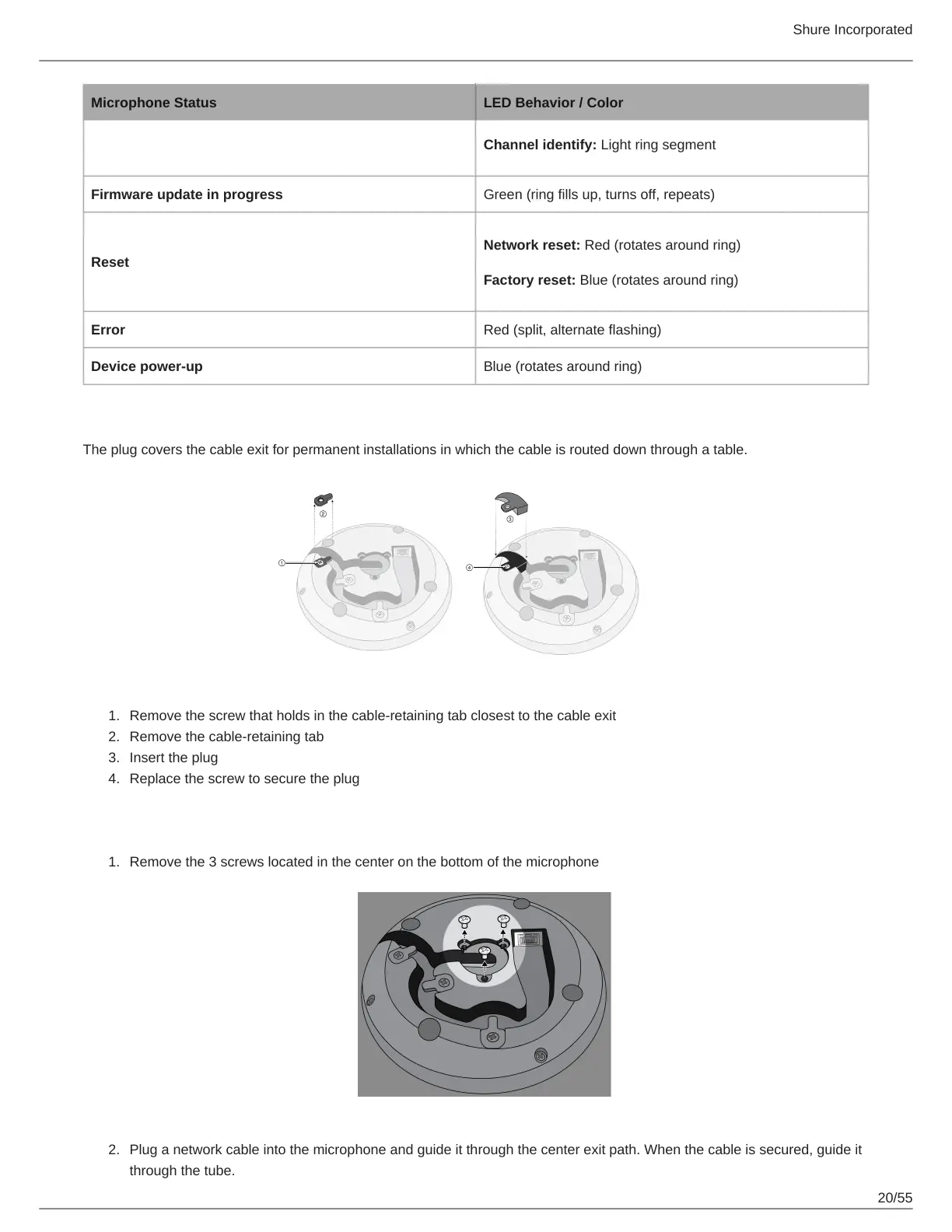
The plug covers the cable exit for permanent installations in which the cable is routed down through a table.
Remove the screw that holds in the cable-retaining tab closest to the cable exit
Remove the cable-retaining tab
Insert the plug
Replace the screw to secure the plug
Permanent Table Installation
Remove the 3 screws located in the center on the bottom of the microphone
Plug a network cable into the microphone and guide it through the center exit path. When the cable is secured, guide it
through the tube.