Shure Incorporated
18/87
Connect a computer to the network switch to provide control of the array microphone and other networked compo
nents through the software control panel.
③ ANI4OUT (digital-to-analog conversion)
Each ANI4OUT receives 4 channels of Dante audio, and converts them to 4 analog signals, delivered through XLR
outputs or block connectors.
Input: Connect the ANI4OUT to the network switch with a network cable
Ouput: Connect the analog output to the audio input on the video codec
④ Video codec connection to far end
Connect the codec to the appropriate network to connect with the far end.
⑤ Audio from far end to amplifier
Route the far end audio through the video codec audio output to an amplifier.
⑥ Amplified audio signal to loudspeakers
Connect the loudspeakers to the amplifier to deliver the audio from the far end.
Hardware
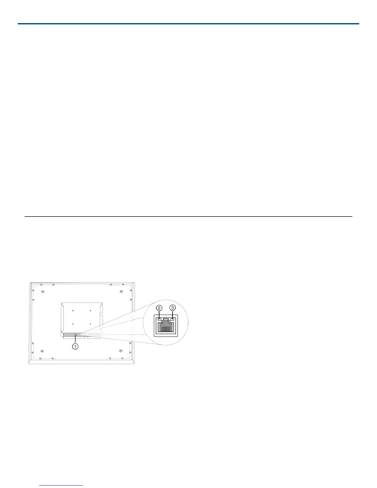
Network Ethernet Port
The network port carries all audio, power, and control data. It is located on the back panel as shown.
① Network Port
RJ-45 jack for network connection.
② Network Status LED (Green)
Off = no network link
On = network link established
Flashing = network link active