When you have completed the right-hand
wiring, remove the terminal strips from the left
hand end piece.
The optional navigation input may be
connected at this time. Parts for this are in
your Accessory Bag. We do not s
upply the
cable for this connection. This input is
diagrammed on the next page.
The gland for this input must be mounted on
the end cap. To locate the hole for the gland,
look on the inside of the end cap. You will
see several places where the plastic has
been formed so that a hole may be easily
drilled. Drill the hole using a 9/32 (7 mm) drill.
Place the gland from the accessory kit in the
hole. Fasten it with the supplied plastic nut
and tighten securely.
Pass the wires numbered "4" and "5" through
the glands in the left hand end cap as shown
in the diagrams labelled," Cable 4, Pump
Motor", and " Cable 5, Power". Using the
same diagrams, wire the left hand terminal
strips. These drawings do not show the gland
for the optional navigation input.
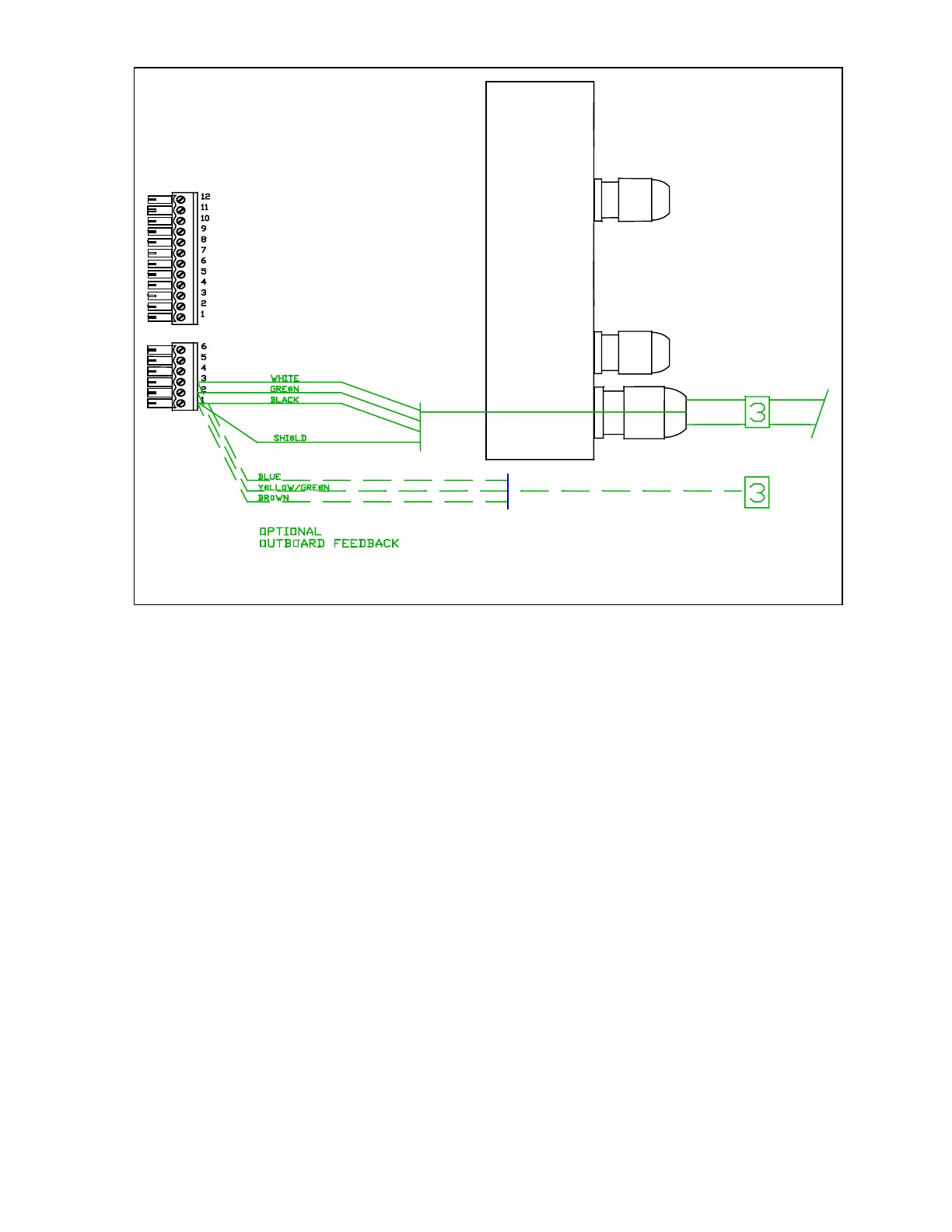
J6
J7
Right-hand side. Cable 3, Rudder Feedback
 Loading...