L
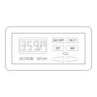
eft hand side showing optional navigation input connection
Use the diagram above to wire the navigation input. The terminal strip for this is in your Accessory
Bag. See your LORAN, GPS, or plotter manual for information about wiring connections from that
unit. The cable shield should be connected only to the Nav device.
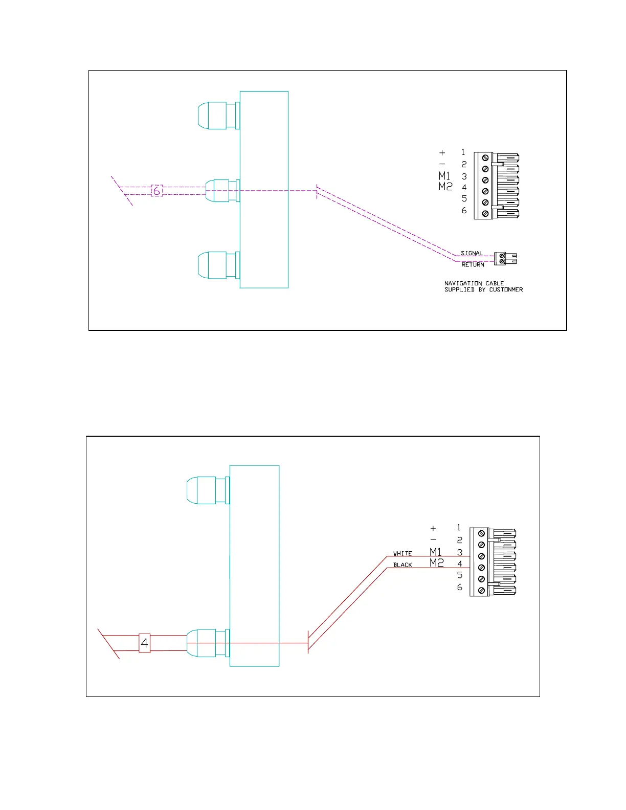
Left hand side. Cable 4, Pump Motor.
Please see appendixes for wiring to other motors or solenoids.
J1
J2
J1
 Loading...