Chapter 4 Operating Instructions
Ranger E/D
24 SICK IVP • Industrial Sensors • www.sickivp.com • All rights reserved 8011731
Hardware Description
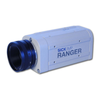
Power I/O connector (male)
Pin Color* Signal Description
1 White In 1 Enable (24 V)
2 Brown Power 24 V power supply
3 Green Out 1 Reserved (B-type)
4 Yellow In 2 Reset (24 V)
5 Gray TRA TRA, RS485
6 Pink TRB TRB, RS485
7 Blue GND Ground
8 Red Out 2 Laser trigger (TTL)
*Color is valid for cable type DOL-1208-
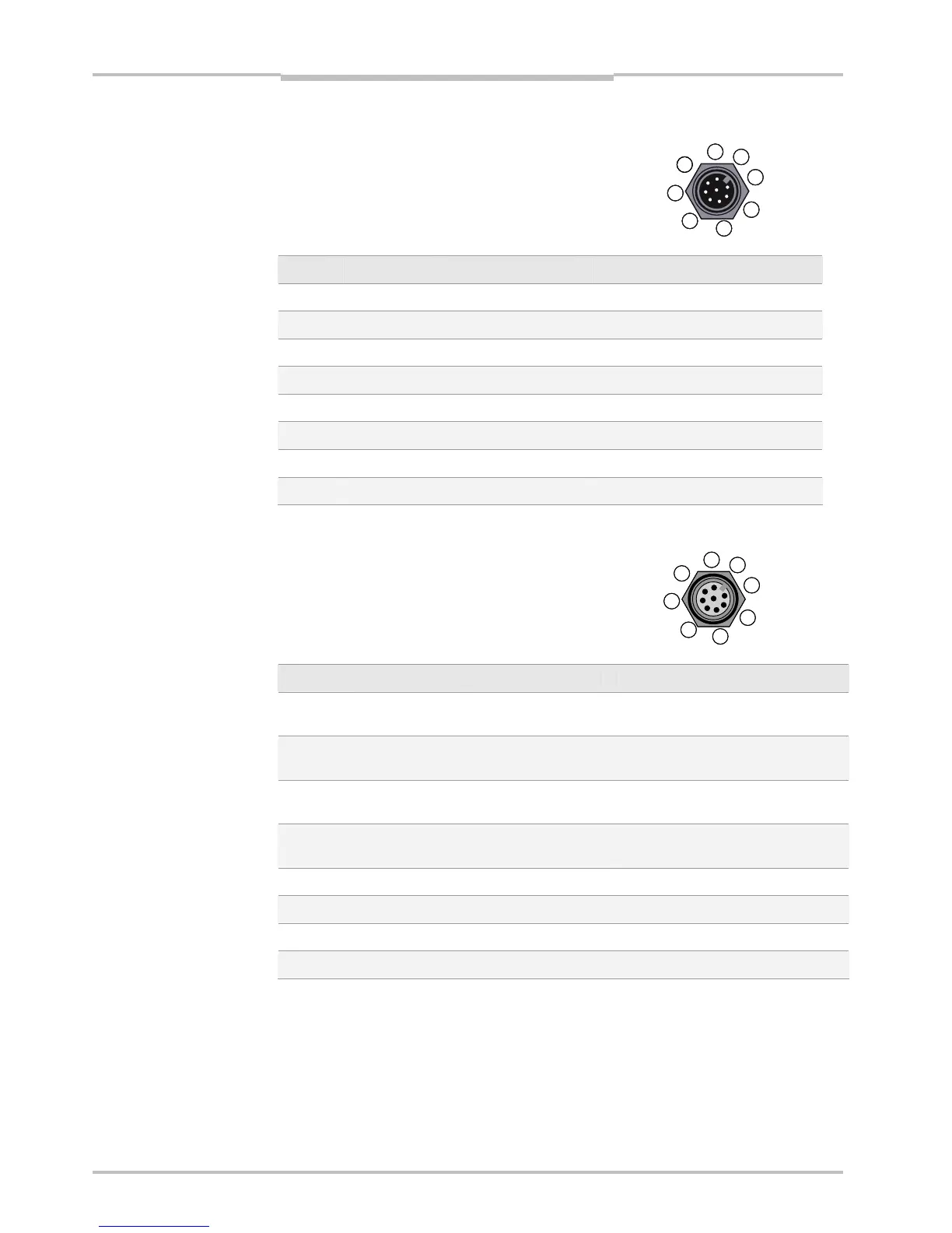
Encoder connector (female)
Pin Color** Signal Description
1 White In_A+ Phase 1, RS422 +
TTL signal level, terminated
2 Brown In_B+ Phase 2, RS422 +
TTL signal level, terminated
3 Green In_B- Phase 2, RS422 -
TTL signal level, tesrminated
4 Yellow In_A- Phase 1, RS422 -
TTL signal level, terminated
5 Gray GND Ground
6 Pink In 3 Reserved (24 V)
7 Blue In 4 Monitor Enable (24 V)
8 Red Out 3 Reserved (B-type)
**Color is valid for cable type STL-1208-
1
2
3
4
5
6
7
8
2
1
7
6
5
4
3
8