Operating Instructions Appendix G
Ranger E/D
8011731 SICK IVP • Industrial Sensors • www.sickivp.com • All rights reserved 33
Ranger E/D Power-I/O terminal
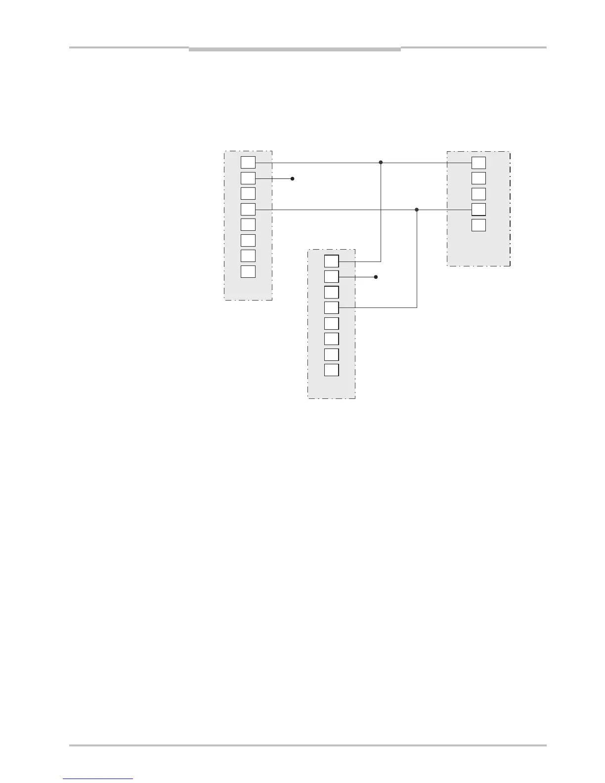
Wiring example B
This example shows a wire diagram for connecting one Sick Stegman RS422 encoder
(DRS-60 with TTL output levels) to two Rangers. In this example all pulses from the en-
coder are interpreted as forward signals.
1
8
5
4
7
6
3
2
1
8
5
4
7
6
3
2
8
10
1
6
5
Figure F.4 – Wiring example – forward signals
G Ranger E/D Power-I/O terminal
The Ranger E/D Power-I/O terminal is used for facilitating the connection of power and I/O
signals to the Ranger. It is connected to the Power I/O and Encoder connectors on the
Ranger E or D by using a Ranger E/D PowerIO-Encoder Y-cable with M12 connectors. The
other end of the cable is connected to a DSUB connector on the Ranger E/D Power-I/O
terminal.
The Power-I/O terminal has screw terminals for connecting I/O signals, and a power plug
for direct connection to the Ranger 24 V DC Power supply.
It also has a push button that when pressed provides 24 V DC to a red wire. This wire is by
default connected to the Reset signal input on the Ranger (on screw terminal 1), but can
easily be connected to other 24 V input signals by moving the wire to another screw termi-
nal. For example, by connecting the wire to the Ranger’s Enable signal (screw terminal 5),
the push button can be used for enabling measurements on the Ranger.
Phase1 RS422+
Phase1 RS422-
GND
GND
Ranger
camera #1
Ranger
camera #2
SICK Stegman
Encoder (RS422)