Chapter 2 Operating Instructions
Ranger E/D
6 SICK IVP • Industrial Sensors • www.sickivp.com • All rights reserved 8011731
Installation Guide
2 Installation Guide
2.1 Preparations
The following parts are recommended for getting started with the Ranger:
The Ranger E or D camera
A PC with a network interface card (NIC) that supports Gigabit Ethernet (for information
on requirements, see Appendix)
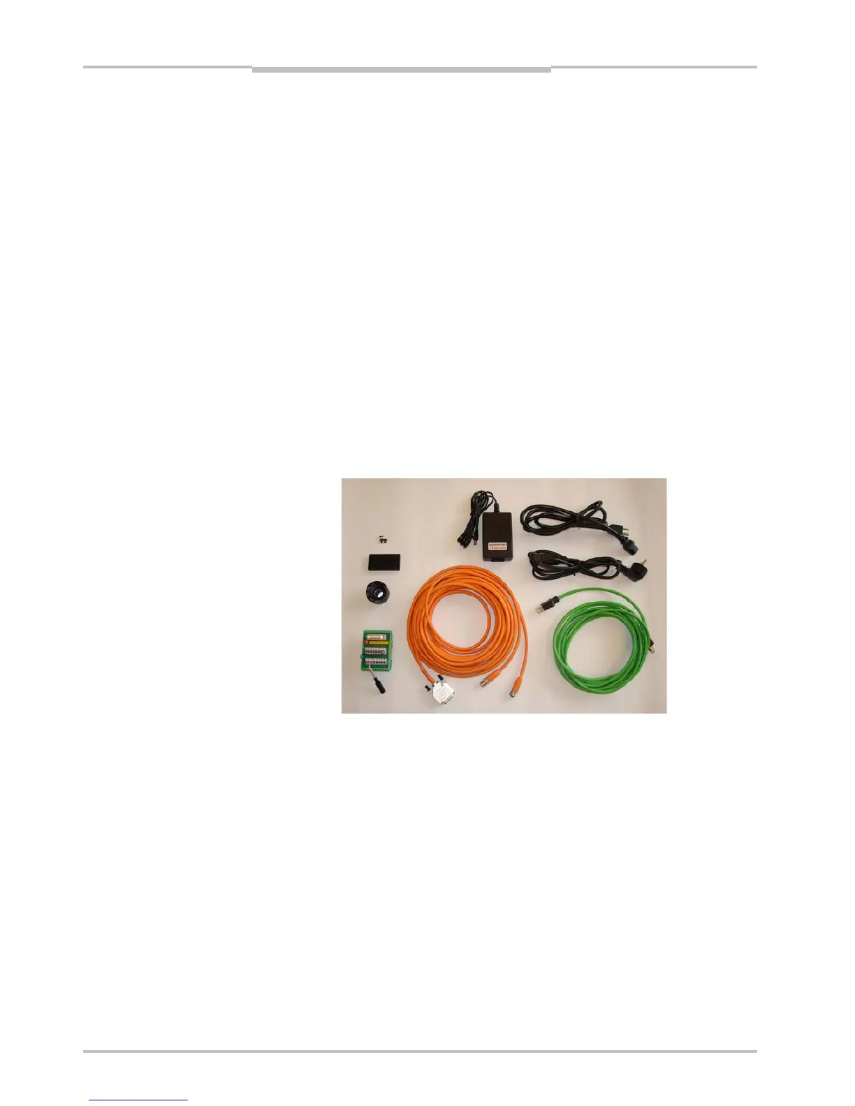
A Ranger E/D accessory kit:
– A Ranger E/D Power-I/O terminal
– An Ethernet cable for Gigabit Ethernet (5 m)
– A Power IO–Encoder Y-cable (2xM12 female – D-SUB male, 2 m)
– A lens, 25 mm F1.4, C-mount 1” optics
– Camera mounting parts
– A power supply (24 V DC wide range power supply with 1m cable and a standard
power input to support US/Europe cord)
– Operating Instructions (printed)
Ranger E/D Development software CD (including Ranger Studio)
Line-projecting laser, 660 nm
Laser triangulation parts
Figure 2.1 – Ranger E accessory kit
Some of parts listed above are recommended but not required for a working Ranger
system. For a minimal Ranger system the following parts are required:
A Ranger E or D camera
A 24 V DC power supply
A C-mount lens
A laser or other suitable light source
A PC with an Ethernet network interface
An Ethernet cable for camera control and data streaming
A PC application that communicates with the Ranger