Chapter 2 Operating Instructions
Ranger E/D
8 SICK IVP • Industrial Sensors • www.sickivp.com • All rights reserved 8011731
Installation Guide
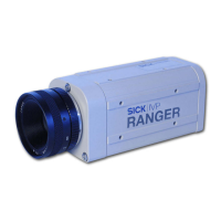
Figure 2.3 – Recommended ways of connecting one or more Rangers to a PC
The recommended IP settings:
Device IP address within the range Net mask
PC 192.168.0.1 – 192.168.0.10 255.255.255.0
Camera 192.168.0.11 – 192.168.0.254 255.255.255.0
Each Ranger needs a unique IP address when connected in a network. The Rangers are
delivered with IP addresses, which by default will work in most cases. If necessary, the IP
address of the Ranger can be changed by using the iCon Device Configuration utility.
Information on using iCon Device Configuration can be found in Appendix E.
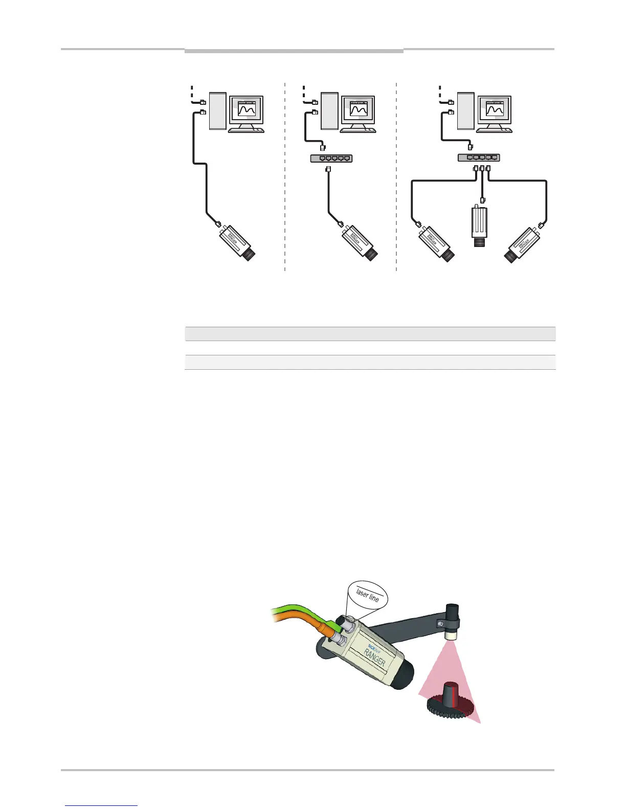
2.2 Mounting the Ranger
When measuring range, the Ranger is used together with a line-projecting laser line that
illuminates the cross-section of the object to be measured. The Ranger and the laser
should be mounted so that the laser illuminates the object from one direction, and the
Ranger views the object from another direction.
The Ranger and the laser line should be oriented so that the laser line will appear along
the sensor in the Ranger. The Laser line mark on the back of the Ranger indicates in which
direction the Ranger will expect the laser line to be.
Exactly how to mount the Ranger and the laser depends on a whole number of factors. For
more information, see “Mounting Rangers and Lightings” in the Reference manual.
Figure 2.4 – Mounting the Ranger and a laser for measuring range.
PC
Switch
PC PC
Switch
Other network