Operating Instructions Chapter 2
Ranger E/D
8011731 SICK IVP • Industrial Sensors • www.sickivp.com • All rights reserved 9
Installation Guide
For best result it is also important to shield out direct sun light and other disturbing light
from the field of view.
It is also important to select a lens that is suitable for the field-of-view in which the Ranger
should measure. Select a high-quality lens that gives sharp images and low distortion, as
this can be essential for achieving a successful vision application.
The Ranger E has four mounting holes on each side, and two additional holes on the
bottom side near the front. The accuracy in location relative to the sensor is higher for the
two front holes than for the other holes. For drilling instructions, dimensions and further
information, see the Hardware Description on page 22.
2.3 Connecting the Ranger
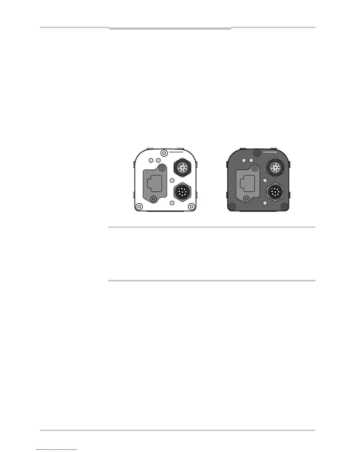
The following figure shows the position of the connectors on the back of the Ranger. For
more information on wiring and signals on the connectors, see the Hardware Description
on page 22.
encoder
Gigabit Ethernet
data
laser line
link
function on
power
encoder
Gigabit Ethernet
data
link
function on
power
laser line
Figure 2.5 – Connectors on the Ranger E and D respectively.
Warning!
Never connect any signals while the Ranger unit is powered.
Never connect a powered Ranger E/D Power-I/O terminal or powered I/O signals to a
Ranger.
If the laser trigger signal is used for lighting the laser, the laser may become activated as
soon as the Ranger is powered on. Do not look into the laser beam. Avoid looking at the
laser reflection.
Follow the following steps to prepare the Ranger for operation.
1. Ensure that all laser safety requirements are fulfilled for the applicable laser system
according to the standards IEC 60825-1 (2001-08) and 21 CFR 1040.10 / 11
(CDRH). See ”Laser Safety” in Appendix B for details.
2. Remove the protection caps covering the connections for Gigabit Ethernet, Power I/O,
and Encoder connectors.
3. Connect the Ethernet cable to the Gigabit Ethernet connector on the Ranger. Connect
the other end of the Ethernet cable to the Network Interface Card (NIC) in the PC, or to
a Gigabit Ethernet switch.
4. Connect any I/O signals to be used to the Power I/O and the Encoder connector on the
Ranger.
The Ranger E/D Power-I/O terminal is useful for connecting I/O signals to the Ranger.
It offers screw terminals for connecting the signals, and connects to the Ranger with a
Ranger E/D PowerIO-Encoder Y-cable.
5. Connect the unpowered power supply to the Power I/O connector on the Ranger, or to
the power plug on the Ranger E/D Power-I/O terminal.
6. Connect the laser to its power supply. If a stronger laser (class IIIb/3B or higher) is
used, the laser power must be connected through a laser safety box.
7. Switch on the power to the system.
a