Operating Instructions Chapter 4
Ranger E/D
8011731 SICK IVP • Industrial Sensors • www.sickivp.com • All rights reserved 23
Hardware Description
Calculation of Sensor Response of the sensor for a given amount of light incident on the
sensor follows the steps below:
Make an approximation of the wavelength content in your light source.
Map the shape of the wavelength content of the light source to the spectral curve of the
sensor above, and read (AD units per pixel)/(µJ/cm
2
) for one or several wavelengths.
Determine the integration time for your application.
Translate the gray value per energy from the curve above to gray value per power by
multiplying the value with the integration time.
Determine the incident light power on the sensor (irradiance, W/m
2
) in your application.
Multiply this value with the sensitivity from step 4. The resulting sensor response is
given as a digital gray value in AD units.
Example:
A laser light source with a maximum incident power of 0.05 W/m
2
(on the sensor area) at
725 nm.
The integration time is 10 ms.
The laser will at 725 nm give a sensitivity of approximately 2600 (AD units per
pixel)/(µJ/cm
2
).
The sensitivity will be 2600 x 10
6
x 10
-4
x (10 x 10
-3
) = 2600 AD units/(W/m
2
).
On the sensor 0.05 W/m
2
will be incident.
The response will be 2600 x 0.05 = 130 AD units per pixel.
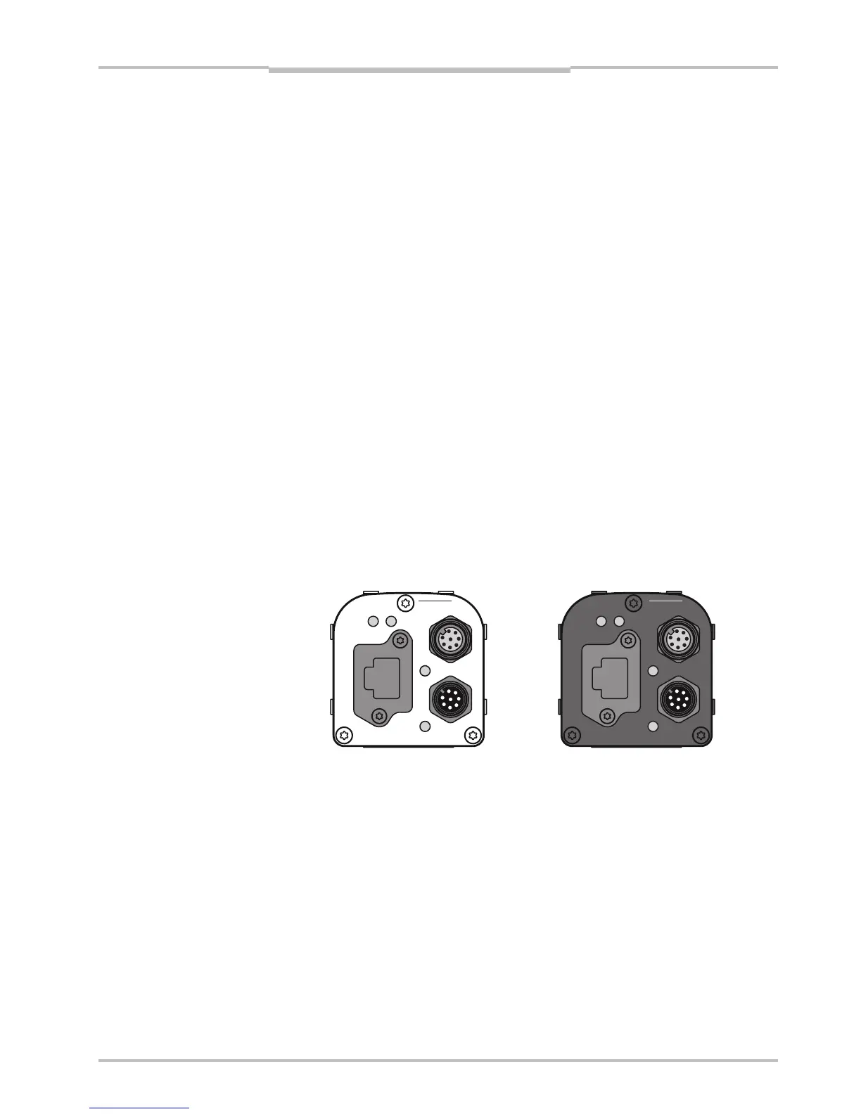
4.2 Electrical Connections
The electrical connections are done with M12 plug-connectors and an Ethernet RJ45
connector. There are three connectors on the back of the Ranger E and D.
encoder
Gigabit Ethernet
data
laser line
link
function on
power
encoder
Gigabit Ethernet
data
link
function on
power
laser line
Figure 4.2 – Back plate of the Ranger E and Ranger D respectively, with
M12 connectors, Ethernet connector, and LEDs
The LEDs on the back plate have the following functions:
LED When lit
On The Ranger is powered.
Link The Ranger is connected to an Ethernet network.
Data The Ranger is sending data over the Ethernet connection.
Function Reserved