Operating Instructions Appendix F
Ranger E/D
8011731 SICK IVP • Industrial Sensors • www.sickivp.com • All rights reserved 31
Connecting Encoders
F Connecting Encoders
Warning
Never connect any signals while the Ranger unit is powered.
Never connect a powered I/O & Encoder Interface unit to a Ranger.
Never connect anything but TTL signal levels to the encoder inputs.
Failure to follow these rules may damage the Ranger unit.
The RS422 inputs on the Ranger E and D have internal termination, which makes it possi-
ble to connect an RS422 encoder to the Ranger without requiring any external termination.
With this termination it is possible to directly connect up to two Rangers to the same
encoder. If more than two Rangers are going to use the same encoder, the encoder and
Rangers should be connected to the Encoder terminal accessory. With this device it is
possible for up to eight Rangers to use the signals from the very same encoder.
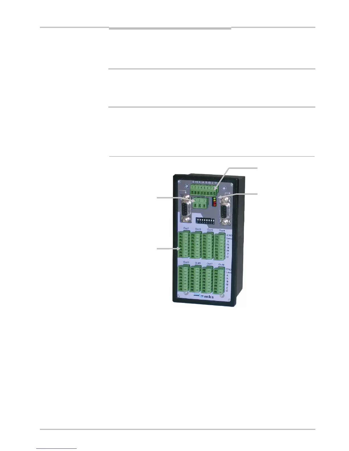
Figure F.2 – Encoder terminal
a
WARNING
Power supply
10–30 V DC
8 outputs to cameras