Appendix F Operating Instructions
Ranger E/D
32 SICK IVP • Industrial Sensors • www.sickivp.com • All rights reserved 8011731
Appendix
The signals from the encoder should be connected to the Ranger’s Encoder connector
according to the following wire diagram.
Table F.3 – Ranger E and D to SICK Stegman Encoder wire diagram
Ranger E and D
Encoder connector SICK Stegman Encoder
Ranger E/D
Power-I/O
terminal
Pin Color* Signal Pin Color Signal Screw terminal
1 White In_A+ 5 White A+ 3
2 Brown In_B+ 8 Pink B+ 4
3 Green In_B- 1 Black B- 7
4 Yellow In_A- 6 Brown A- 6
5 Gray GND 10 Blue GND 15
*Color is valid for cable type STL-1208-
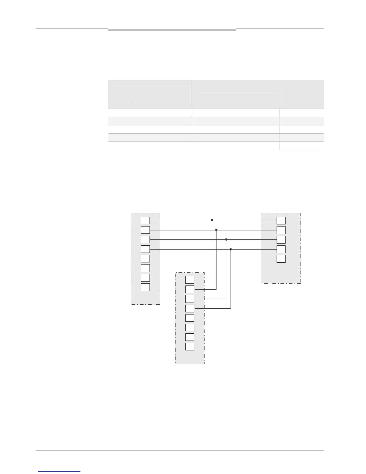
Wiring example A
This example shows a wire diagram for connecting one Sick Stegman RS422 encoder
(DRS-60 with TTL output levels) to two Rangers. In this example the encoder is connected
for both forward and backward signals.
1
8
5
4
7
6
3
2
1
8
5
4
7
6
3
2
8
10
1
6
5
Figure F.3 – Wiring example – forward and backward signals
Phase1 RS422+
Phase2 RS422+
Phase2 RS422-
Phase1 RS422-
Ranger
camera #1
Ranger
camera #2
SICK Stegman
Encoder (RS422)