Chapter 5 Addendum Operating Instructions
C2000 Eco
30 © SICK AG • Industrial Safety Systems • Germany • All rights reserved 8011905/TI60/2010-02-12
Subject to change without notice
Electrical installation and
configuration
GB
5 Electrical installation and configuration
During the electrical installation of the C2000 Eco safety light curtain, observe the follow-
ing notes in addition to the information in the “C2000 Safety Light Curtain” operating
instructions:
To ensure full electromagnetic compatibility (EMC), functional earth (FE) must be
connected.
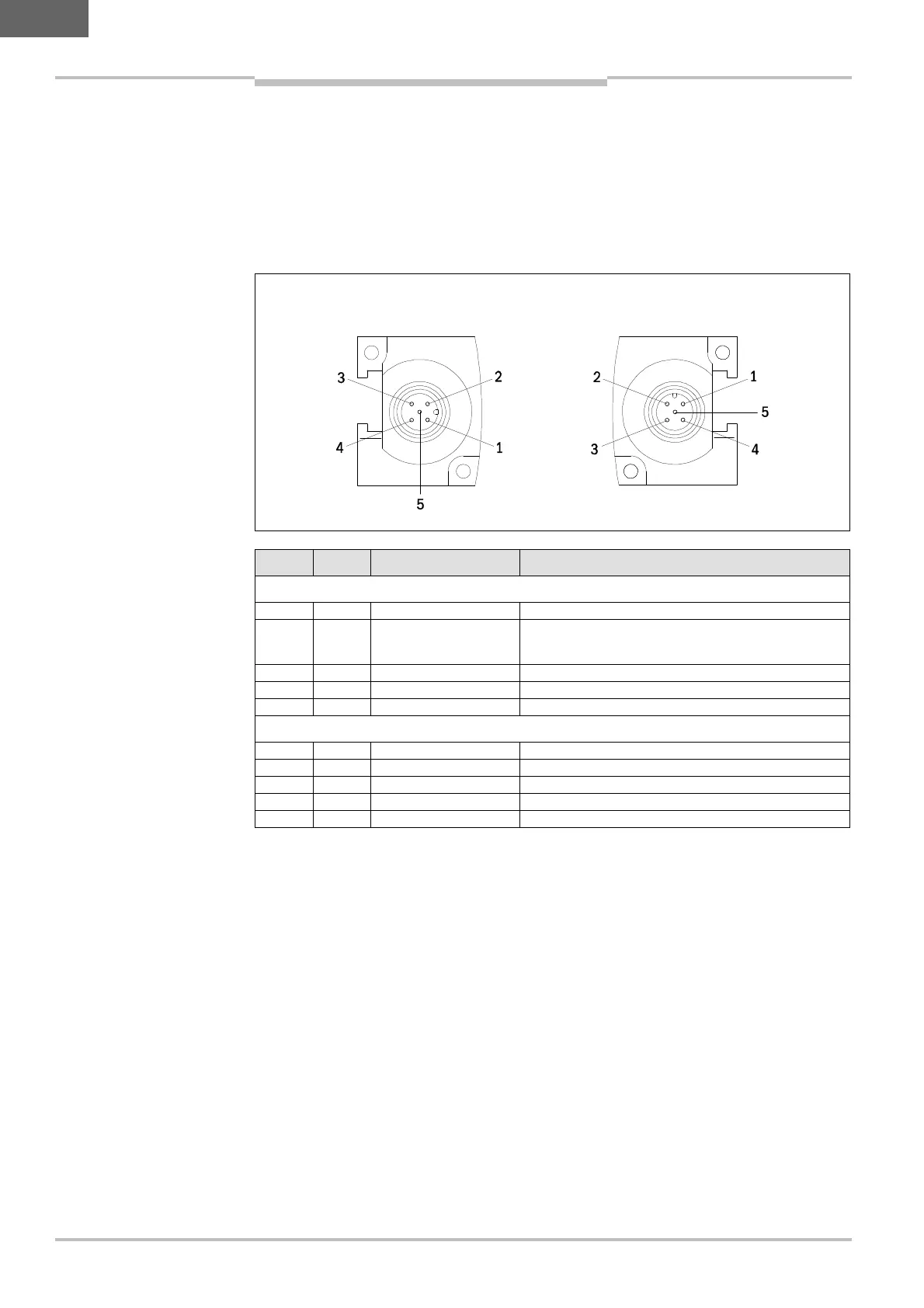
Pin no. Colour Designation Meaning (I = input, O = output)
Sender
1 Brown 24 V DC Voltage supply U
B
2 White Test I: device self-test
0 V = sender inactive
24 V = sender active
3 Blue GND 0 V DC, voltage supply
4 Black nc Reserved
5 Grey Shield Functional earth
Receiver
1 Brown 24 V DC Voltage supply U
B
2 White OSSD 1 O: output signal switching device 1
3 Blue GND 0 V DC, voltage supply
4 Black OSSD 2 O: output signal switching device 2
5 Grey Shield Functional earth
5.1 Device configuration
The device configuration is described in the following chapters of the “C2000 Safety Light
Curtain” operating instructions:
chapter 5.4.1 Configuration of the device self test
chapter 5.4.2 Configuration of the cyclic system test
the functions
beam coding
EDM (external device monitoring)
RES (restart interlock)
are not available on the C2000 Eco safety light curtain.
M12 plug 5-pin