Chapter 4 Technical Information
CLV61x bar code scanner
18 © SICK AG · Germany · All rights reserved · Subject to change without notice 8015592/ZNI9/2017-06-13
Electrical installation
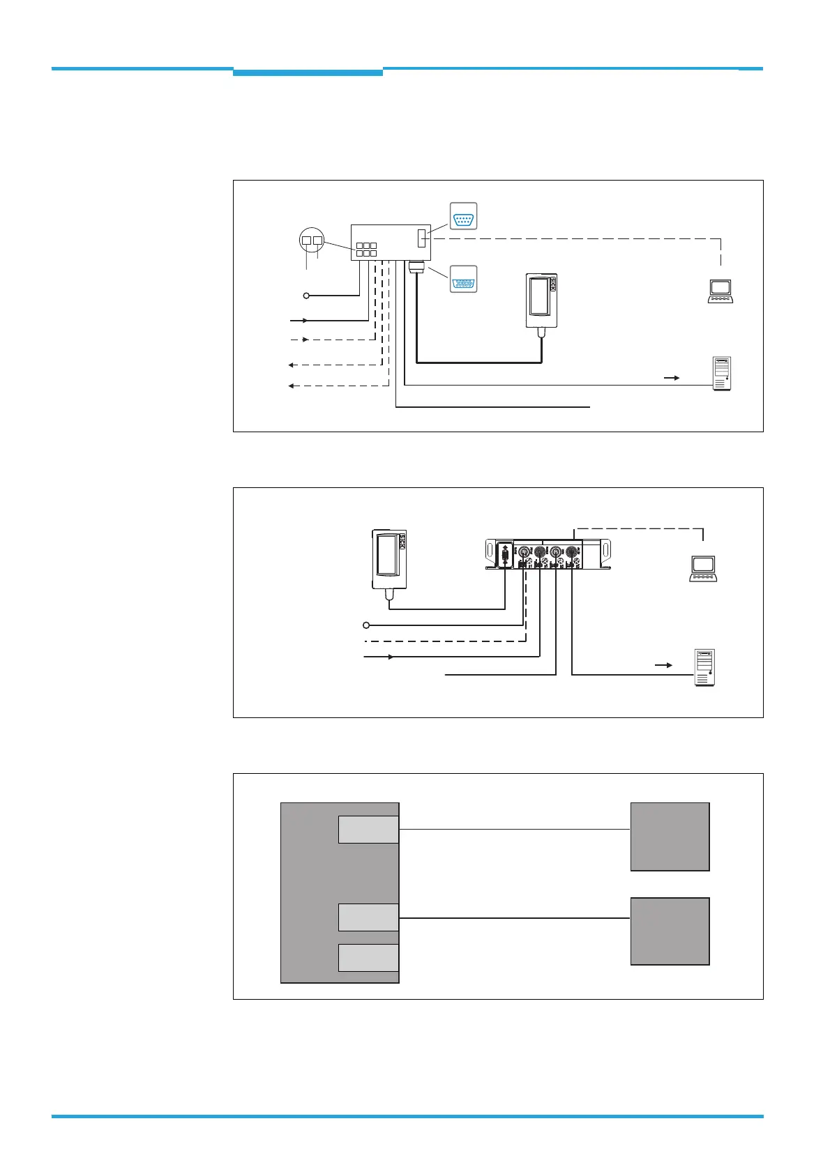
4.2 Overview of all lnterfaces and Connection Options
CLV61x ECO/CAN
CLV61x FIELDBUS
Using the Data Interfaces
Input 2
(e.g. incremental encoder,
Teach-in matchcode)
Input 1
(e.g. external reading clock)
Output 1
(e.g. indicator lamp)
Output 2
(e.g. indicator lamp)
CLV61x ECO/CAN
CDB620
Connection module
SerialSerial
Configuration
Diagnostics
SOPASSOPAS
SerialSerial
“HOST (RS-232)/
AUX (RS-232)/
I/O”
...
...
1
2
DC 10 V ... 30 V
GND
HOST
PC
Further data
processing
e.g. cable no. 2014054 (2 m)
“AUX” (RS-232)
DC 10 V ... 30 V
Switching inputs/outputs = digital
“HOST” (RS-232)
Reading result
“CAN” (CLV61x CAN only)
CAN Sensor Network
Configuration
Diagnostics
SOPASSOPAS
“AUX (RS-232)/
CAN/DC 10 V ... 30 V”
PLC
PC
Further data
processing
e.g. cable
no. 6036106
(2 m)
DC 10 V ... 30 V
“AUX” (USB)
Reading result
CLV61 FIELDBUS
CAN Sensor Network
PROFIBUS
PROFIBUS
CDF600-21xx
PROFIBUS
Fieldbus module
Input 1
(e.g. external reading clock)
CLV61x
Aux
RS-232
RS-232
CAN
*)
SOPAS ET
Configuration
Software
Further data
processing
Host
PC
HOST
*) CLV61x CAN and FIELDBUS series
◂ Configuration/data output ▸
◂ Configuration/data output ▸
 Loading...


