Chapter 4 Technical Information
CLV61x bar code scanner
20 © SICK AG · Germany · All rights reserved · Subject to change without notice 8015592/ZNI9/2017-06-13
Electrical installation
4.4 Pin Assignments and Lead Color Assignments of Cables
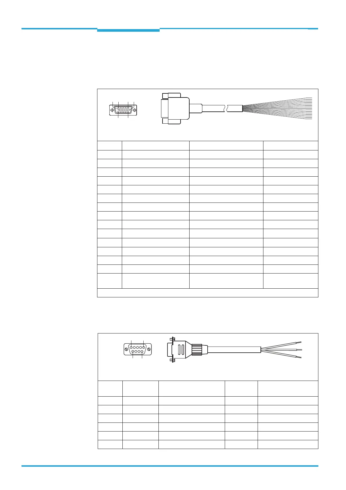
4.4.1 Connection: CLV61x to a customer-specific Connection Box
Extension Cable No. 2043413 (2 m), open end
ss
4.4.2 Connection: CDB620-001 Connection Module to PC (HOST interface RS-232)
RS-232 Data Cable No. 2030319 (3 m), open end
Pin Signal Function Color of lead
1 DC 10 V ... 30 V Supply voltage Red
2 RxD (RS-232), Aux AUX interface (receiver) Purple
3 TxD (RS-232), Aux AUX interface (transmitter) Yellow
4 Sensor 2 Switching input 2 Red + black
5GND Ground Black
6N.c. – Light blue
7 RxD (RS-232), Host HOST interface (receiver) Blue
8 N.c. – Light gray or turquoise
9 TxD (RS-232), Host Host interface (transmitter) Green
10
CAN H
*)
CAN-Bus (IN/OUT) Gray
11
CAN L
*)
CAN-Bus (IN/OUT) Pink
12 Result 1 Switching output 1 Brown
13 Result 2 Switching output 2 Orange
14 Sensor 1 Switching input 1 White
15 SensGND Common ground for all switch-
ing inputs
White + black
*) Only with CLV61x CAN and CLV61x FIELDBUS series
Pin Signal Function Color of lead CDB620-001 terminals/
CDM420-0001 terminal
1– – – –
2 RxD (RS-232) Host interface (receiver) Brown 43 / 34 (TxD Host)
3 TxD (RS-232) Host interface (transmitter) Blue 44 / 35 (RxD Host)
4– – – –
5 GND Ground Black 42 / 36 (GND)
6 ... 9 – – – –
15-pin D-Sub HD socket
(front view)
Braid shield contacted with metal housing of socket.
110
15
6
11
5
9-pin D-Sub socket
(front view)
5
1
9
6

 Loading...


