Chapter 4 Technical Information
CLV61x bar code scanner
24 © SICK AG · Germany · All rights reserved · Subject to change without notice 8015592/ZNI9/2017-06-13
Electrical installation
4.6 Installation steps
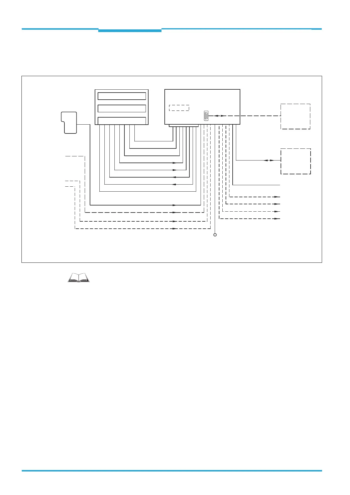
4.6.1 Block diagram: Wiring the CDB620-001/CDM420-0001 Connection Module
The commissioning/configuration of the connection modules as well as the technical data
are described in the:
"CDB620 connection module" operating instructions (part no. 8012119, Ger./Engl.
version) e.g. via www.sick.com/CDB
"CDM420-0001 connection module" operating instructions (part no. 8010004, Ger./
Engl. version) e.g. via www.sick.com/CDM.
The corresponding operating instructions are enclosed in printed form with the connection
modules.
Important! Wiring the Signals without SICK Connection Module
If a customer-specific connection box is used, the wiring in principle of the data interfaces
and switching interfaces signals can be designed according to the following wiring diagrams
for the SICK connection modules (from page 29 on).
If the 15-pin D-Sub HD plug of the CLV61x is not compatible with the customer-specific con-
nection box, the extension cable no. 2043413 (2 m) with corresponding socket and open
leads is available. See Chapter 4.4.1 Connection: CLV61x to a customer-specific Connec-
tion Box, Page 20.
“DC 10 V ... 30 V”
“Sensor 2”
“Host 1” (serial)
“Aux 1” (serial)
“Result 2”
“Result 1”
“CAN”
1)
“Sensor 2”
“Sensor 1”
“External input 2”
2)
“External input 1”
2)
“Sensor 1”
DC 10 V ... 30 V
Application
Scanner
Interfaces
“AUX”
PC
HOST/PLC
PLC
CAN bus
1)
PLC
“Result 1”
“Result 2”
PLC
PLC
“External output 1”
2)
“External output 2”
2)
CDB620-001/CDM420-0001
Connection module
CLV61x
Photo-
electric
switch
Reading clock
Incremental
encoder
Path increment
Further
functions
“HOST” (serial)
“AUX” (serial)
RS-232
RS-232
CMC600
1) NOT for CLV61x ECO series
2) An optional CMC600 Parameter Cloning Module is required to provide the additional switching inputs and outputs
Futher data
processing
Configuration
Diagnosis
2)

 Loading...


