Chapter 4 Technical Information
CLV61x bar code scanner
40 © SICK AG · Germany · All rights reserved · Subject to change without notice 8015592/ZNI9/2017-06-13
Electrical installation
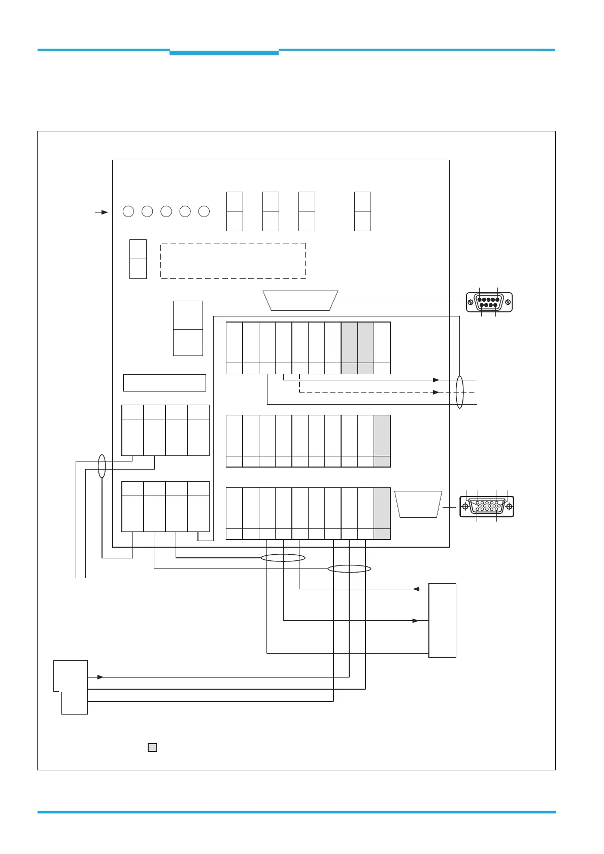
4.8 Using the CDM420-0001 Connection Module
4.8.1 Wiring overview (one switching input used)
ON
OFF
ON
OFF
ON
OFF
CDM420-0001 Connection module
CMC600 parameter cloning module
(optional)
0.8 A T
S8
No CMC ->
SCANNER
AUX interface
6110 5
1115
LEDs
31 32 33 34 35 36 37 38 39 40
T‒/TxD
R‒/RxD
+24 V*
Sensor 1
Aux Out 1
GND
GND
SGND
CAN_H
CAN_L
11 12 13 14 15 16 17 18 19 20
Result 1
Result 2
Aux In 2
Aux In 1
SGND
GND
GND
SGND
internal
internal
21 22 23 24 25 26 27 28 29 30
T+
R+
+24 V*
Sensor 2
Aux Out 2
GND
GND
SGND
CAN_H
CAN_L
1234
+24 V
+24 V
GND
GND
5678
Shield
Shield
Shield
Shield
POWER
Sensor 1
Sensor 2
Result 1
Result 2
S1
POWER
ON
OFF
S2 S3 S4 S6
ON
OFF
ON
OFF
RS485
Term422
TermCAN
SGND
to
CLV61x
15
69
to PC
Pin
2: RxD
3: TxD
5: GND
Result 1
PLC
GND
Result 2
External
reading clock sensor
(e.g. photo- electric switch)
V
S
Out
GND
TxD
Host
RxD
GND
RS-232
= An CMC600 is required to provide the additional switching inputs and outputs
V
S
= DC 10 V ... 30 V on terminal +24 V = +24 V* after fuse F and switch S1
F
V
S
= DC 10 V ... 30 V
RS-232

 Loading...


