Chapter 4 Technical Information
CLV61x bar code scanner
30 © SICK AG · Germany · All rights reserved · Subject to change without notice 8015592/ZNI9/2017-06-13
Electrical installation
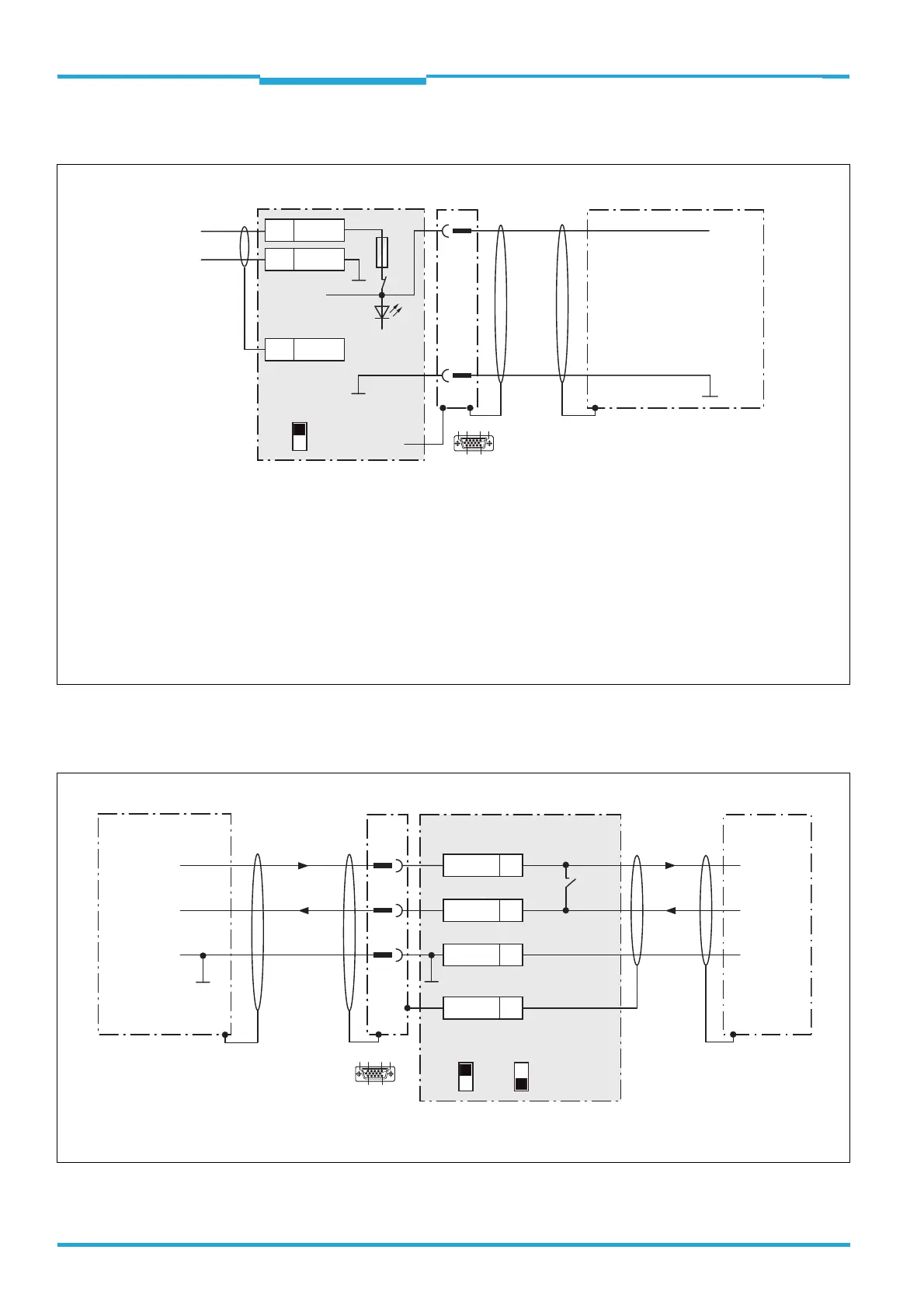
4.7.2 Wiring the Supply Voltage in the CDB620-001 Connection Module
4.7.3 Wiring the RS-232 serial Host Data Interface in the CDB620-001 Connection
Module
6
1
10
5
11
15
CLV61x
CDB620
V
S
V
S
1
5
5
Shield
1U
IN
2 GND
U
IN
*
GND
S1
F
Shield
D-Sub HD plug,
15-pin
GND
.
.
.
.
.
.
ON
OFF
S1 : POWER
DC 10 V to 30 V
U
IN
*
Switch S1:
ON:
Power supply voltage U
IN
switched to U
IN
*
via fuse to CDB620 and CLV61x.
Power supply voltage U
IN
* additionally available on terminals 11 and 14.
OFF:
CDB620 and CLV61x disconnected from power supply voltage.
Recommended position during all electrical installation work.
POWER
V
S
= DC 10 V to 30 V on terminal U
IN
= U
IN
* after fuse F and switch S1
6
1
10
5
11
15
CLV61x CDB620 Host
D-Sub
HD plug,
15-pin
5
.
.
.
TxD
RxD
RxD
TxD
GND
GND
GND
9
7
43
T‒/TxD
44
R
‒/RxD
42
GND
6
Shield
RS-232 RS-232
422
485
S6 : RS
ON
OFF
S7: Term 485
S6
422485

 Loading...


