Chapter 4 Technical Information
CLV61x bar code scanner
48 © SICK AG · Germany · All rights reserved · Subject to change without notice 8015592/ZNI9/2017-06-13
Electrical installation
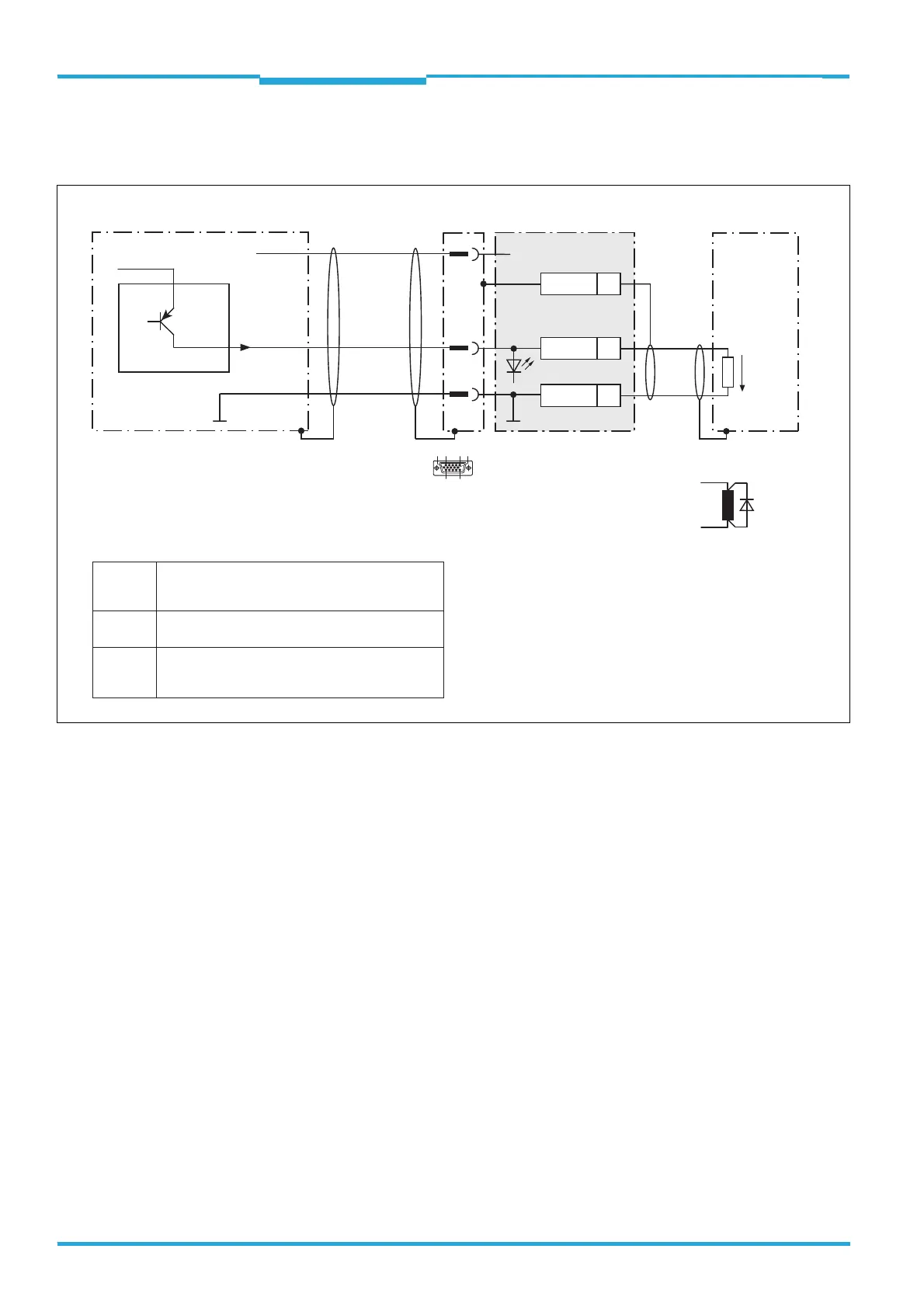
4.8.10 Wiring the "Result 2" Switching Output in the CDM420-0001 Connection
Module
6
1
10
5
11
15
CLV61x
CDM420-0001
V
S
= DC 10 V to 30 V
Load (e.g. PLC)
D-Sub HD plug,
15-pin
13
5
.
.
.
15
Result 2
16
GND
5
Shield
+24 V* (V
S
)
V
S
GND
Quenching circuit:
Install an anti-surge
diode directly at the
load!
For inductive load:
V
OUT
Result 2
Result 2
GND
1
Ratings for "Result 2" switching output
PNP switching against the supply voltage V
S
(+24 V*)
(default setting: Good Read, 100 ms
logic: not inverted [active high])
– Short-circuit proof + temperature protected
– Galvanically not separated from V
S
(+24 V*)
0 V ≤ V
out
≤ V
S
Guaranteed:
(V
S
− 1.5 V) ≤ V
out
≤ V
S
with I
out
≤ 100 mA
Switching
behavior
Features
Electrical
values

 Loading...


