■
The Ethernet connection of the device is used: see "Assembly with use of the
Ethernet connection", page 23
■
The Ethernet connection of the device is not used: see "Assembly without use
of the Ethernet connection", page 25
■
Use of the specified cables, see "Cables", page 40
6.2 Prerequisites for safe operation of the device in a system
See operating instructions of the relevant fixed mount bar code scanner.
6.3 Pin assignment of the connections
Figure 20: M12 female connector, 4-pin, D-coded
Table 7: Ethernet version: Pin assignment of the female connector
Pin Signal Function
1 TD+ Sender+
2 RD+ Receiver+
3 TD– Sender–
4 RD– Receiver–
– – Shield
3
1
7
2
6
5
4
8
13
14
17
15
9
10
12
16
11
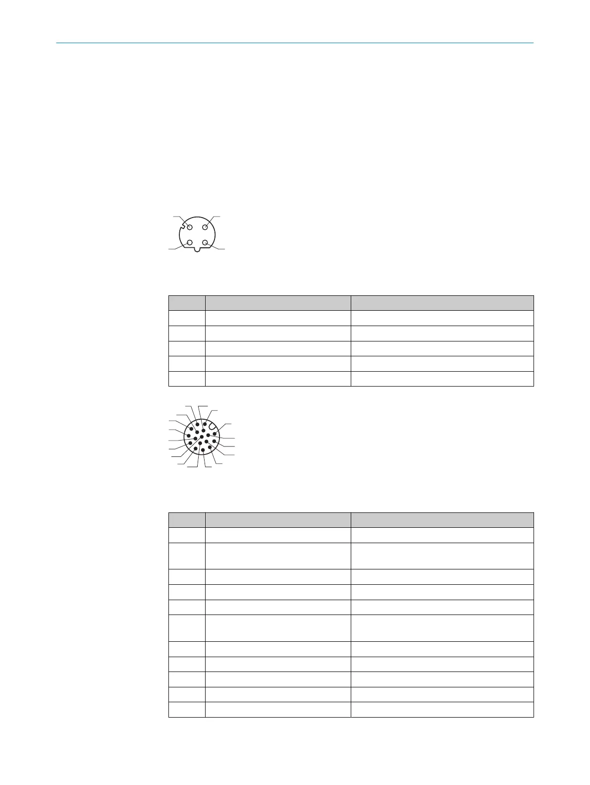
Figure 21: Male connector, M12, 17-pin, A-coded
Table 8: Ethernet version: Pin assignment of the male connector
Pin Signal Function
1 GND Ground
2 CLV62x: 10 V DC ... 30 V DC
CLV63x, CLV64x: 18 V DC ... 30 V DC
Supply voltage
3 CAN L CAN bus (IN/OUT)
4 CAN H CAN bus (IN/OUT)
5 TD+ (RS-422/485) Host interface (sender+)
6 TD– (RS-422/485);
TxD (RS-232)
Host interface (sender-)
7 TxD (AUX) AUX interface (sender)
8 RxD (AUX) AUX interface (receiver)
9 SensGND Digital input ground
10 Sensor 1 Digital input (external reading cycle)
11 RD+ (RS-422/485) Host interface (receiver+)
ELECTRICAL INSTALLATION 6
8021479/19ZB/2021-10-29 | SICK T E C H N I C A L I N F O R M A T I O N | CLV62x, CLV63x and CLV64x with IP69K Protective Housing
29
Subject to change without notice

 Loading...


