11. Tighten coupling nut of the connected connection cable.
12. Position O-rings in the provided grooves of the protective double bushing.
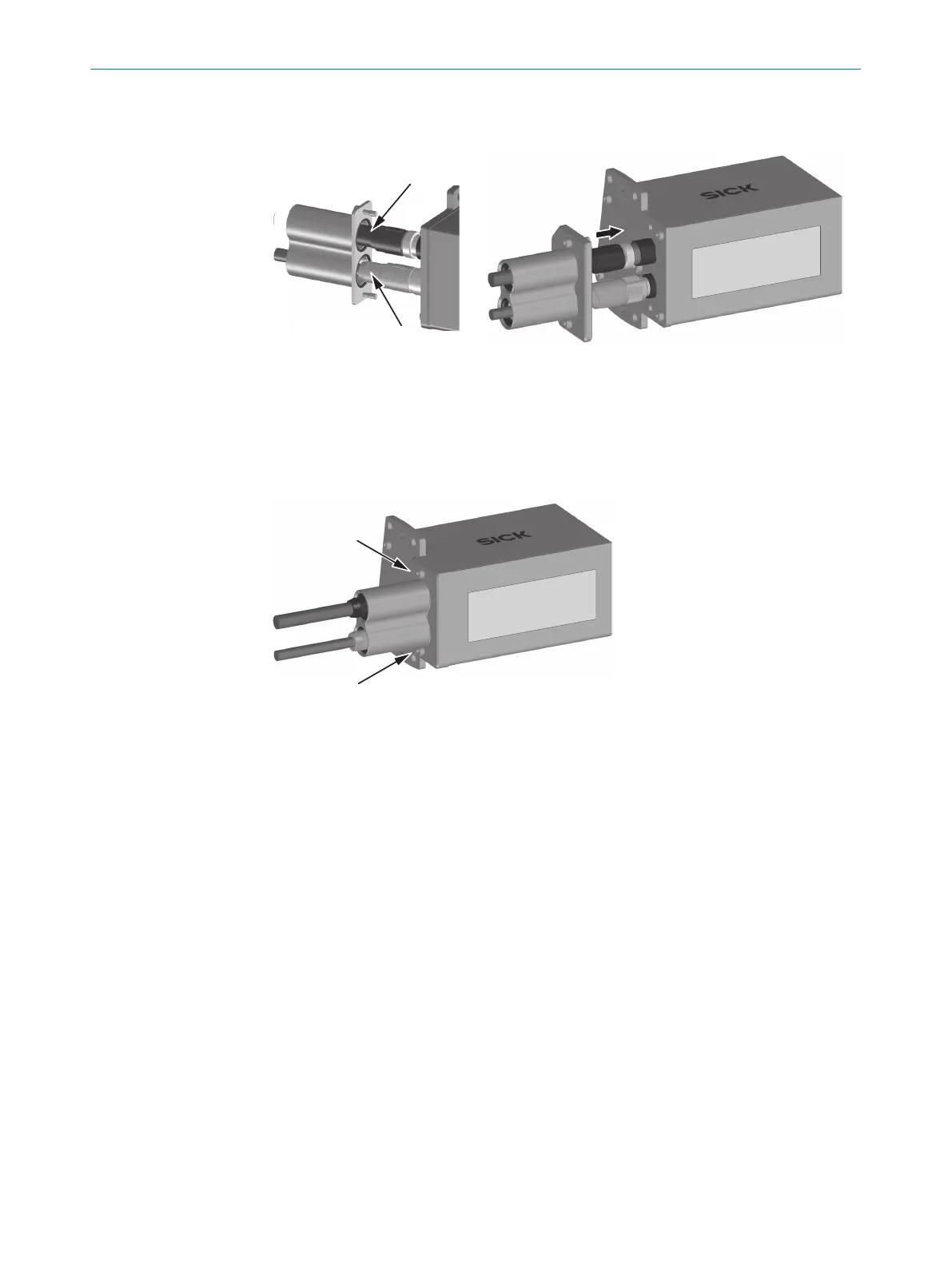
Figure 15: Assembly of IP69K protective housing, with use of the Ethernet connection – Step 3
13. Apply a small amount of lubricant, e.g., Vaseline to the indicated locations. This
makes it easier to slide the protective double bushing over the plug connectors.
14. Carefully push the protective double bushing over the plug connectors.
15. Make sure that the O-rings are correctly positioned in the grooves of the protective
double bushing.
Figure 16: Assembly of IP69K protective housing, with use of the Ethernet connection – Step 4
16. Mount the protective double bushing on the protective housing using the two
screws provided.
5.4.2 Assembly without use of the Ethernet connection
Mounting the protective double bushing on the protective housing
The assembly procedure is described for the protective housing with front viewing
window. The protective housing for fixed mount bar code scanners with oscillating
mirror and side viewing window is assembled analogously.
MOUNTING 5
8021479/19ZB/2021-10-29 | SICK T E C H N I C A L I N F O R M A T I O N | CLV62x, CLV63x and CLV64x with IP69K Protective Housing
25
Subject to change without notice

 Loading...


