2
Plug connector of connection cable for “Ethernet” connection
3
O-ring 11.0 mm x 4.0 mm
4
Protective double bushing
5
“Ethernet” connection, female connector, M12, 4-pin, D-coded
6
Protective housing, here for fixed mount bar code scanners with front viewing window
7
“Power/Serial Data/CAN/I/O” connection, male connector, M12, 17-pin, A-coded
8
O-ring 13.5 mm x 3.0 mm
9
Plug connector of connection cable for “Power/Serial Data/CAN/I/O” connection
ß
Connection cable for “Power/Serial data/CAN/I/O” connection
When delivered, both connections on the protective housing are sealed off with a
protective element.
Auxiliary equipment required
•
Lubricant such as Vaseline
1. Position the device at the operating location.
2. Unscrew the protective element from the 4-pin female connector. Turn the protec‐
tive element counterclockwise for this purpose.
3. Unscrew the protective element from the 17-pin male connector. Turn the protec‐
tive element counterclockwise for this purpose.
Figure 13: Assembly of IP69K protective housing, with use of the Ethernet connection – Step 1
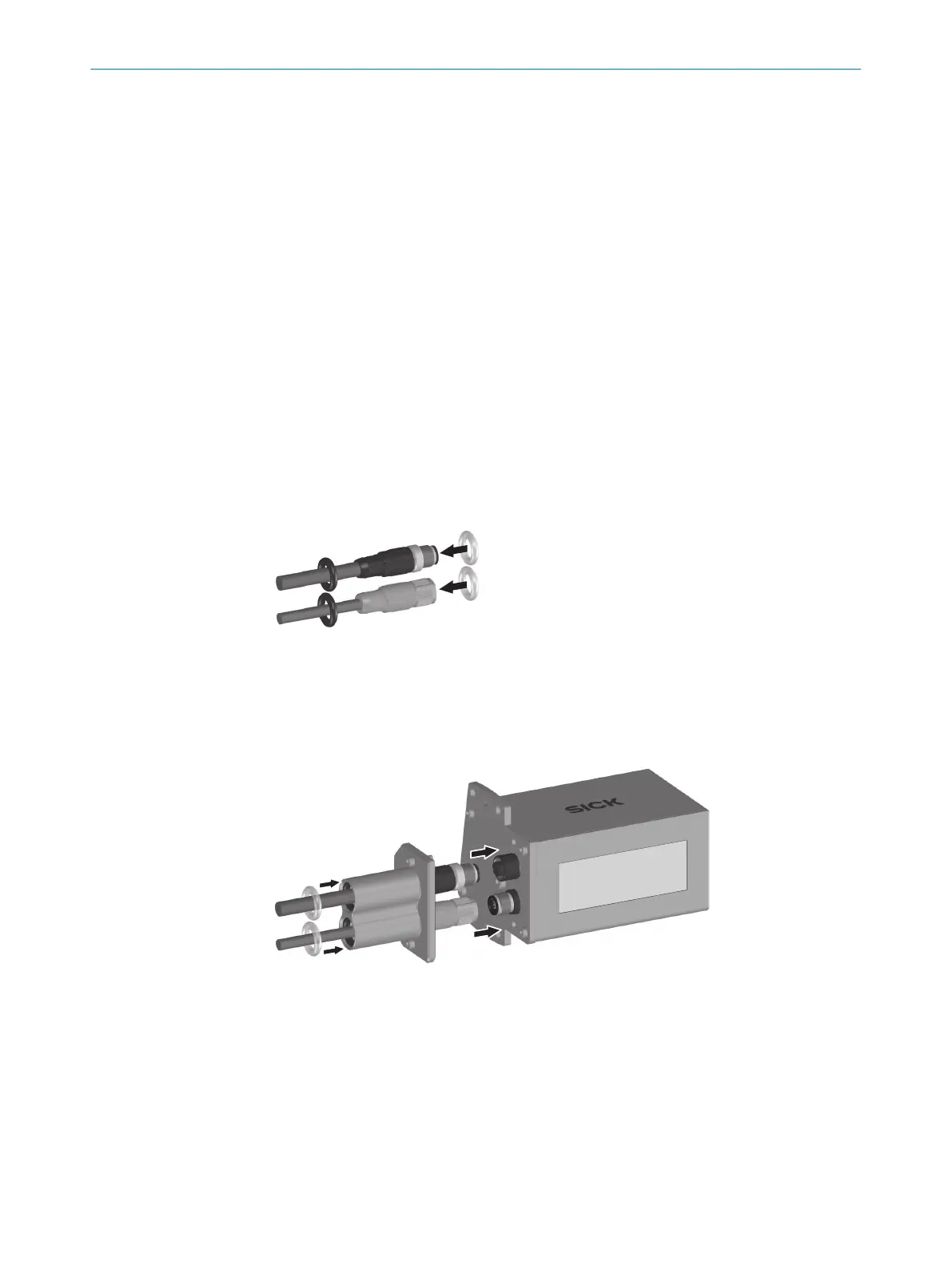
4. Guide the 13.5 mm x 3,0 mm O-ring over the plug connector of the “Power/Serial
data/CAN/I/O” connection cable.
5. Guide the 11.0 mm x 4.0 mm O-ring over the plug connector of the “Ethernet”
connection cable.
Figure 14: Assembly of IP69K protective housing, with use of the Ethernet connection – Step 2
6. Guide plug connector of the “Ethernet” connection cable through the protective
double bushing.
7. Connect “Ethernet” connection cable to the M12 female connector of the protec‐
tive housing.
8. Tighten coupling nut of the connected connection cable.
9. Guide the plug connector for the “Power/Serial Data/CAN/I/O” connection cable
through the protective double bushing.
10. Connect the “Power/Serial Data/CAN/I/O” connection cable at the M12 male
connector of the protective housing.
5
MOUNTING
24
T E C H N I C A L I N F O R M A T I O N | CLV62x, CLV63x and CLV64x with IP69K Protective Housing 8021479/19ZB/2021-10-29 | SICK
Subject to change without notice

 Loading...


