Component overview
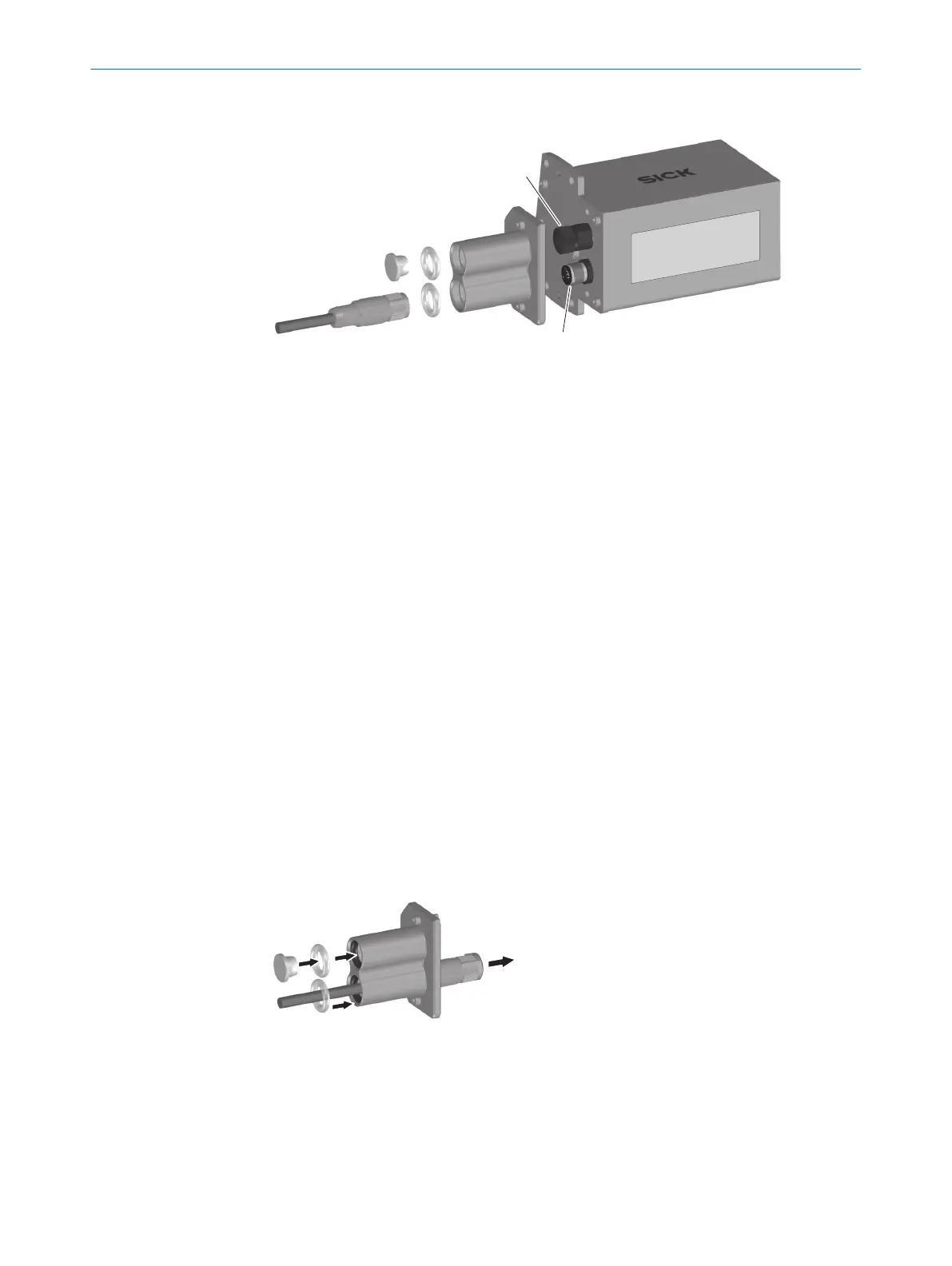
Figure 17: Assembly of IP69K protective housing, without use of the Ethernet connection
1
Protective element for “Ethernet” pass-through
2
O-ring 11.0 mm x 4.0 mm
3
Protective double bushing
4
Protective element for unused Ethernet connection, female connector, M12, 4-pin, D-
coded
5
Protective housing, here for fixed mount bar code scanners with front viewing window
6
“Power/Serial Data/CAN/I/O” connection. male connector, M12, 17-pin, A-coded
7
O-ring 13.5 mm x 3.0 mm
8
Plug connector of connection cable
9
Connection cable for “Power/Serial data/CAN/I/O” connection
When delivered, both connections on the protective housing are sealed off with a
protective element.
Auxiliary equipment required
•
Lubricant such as Vaseline
1. Make sure that the protective plug of the Ethernet connection is securely tight‐
ened.
2. Guide connection cable through the protective double bushing. Seal the lower
feedthrough with the O-ring. Connect the connection cable at the protective hous‐
ing, see "Assembly with use of the Ethernet connection", page 23
3. Position the 11.0 mm x 4.0 mm O-ring in the groove of the upper pass-through of
the protective double bushing.
4. Close off the upper pass-through of the protective double bushing with the sup‐
plied protective element.
Figure 18: Assembly of IP69K protective housing, without use of the Ethernet connection –
protective element
5. Apply lubricant. Push the protective double bushing over the plug connector and
the Ethernet connection. Mount the protective double bushing on the protective
housing, see "Assembly with use of the Ethernet connection", page 23
5
MOUNTING
26
T E C H N I C A L I N F O R M A T I O N | CLV62x, CLV63x and CLV64x with IP69K Protective Housing 8021479/19ZB/2021-10-29 | SICK
Subject to change without notice

 Loading...


