2
Connection module (optional, CDB620 here as example)
3
Device
4
Null modem cable (female connector, D-Sub, 9-pin/female connector, D-Sub, 9-pin),
crossed TxD and RxD
5
Configuration or diagnostics
6
Data further processing
7
Read result
8
Serial variant: Device cable with male connector, D-Sub-HD, 15-pin
9
Digital switching output 2, e.g. for connecting an LED
ß
Digital switching output 1, e.g. for connecting an LED
à
Digital switching input 2, e.g., for connecting an incremental encoder
á
Digital switching input 1, e.g., for connecting a read cycle sensor
"Ethernet" (Host 2)
Input 1 â
Device 3
"Serial RS-232/RS-422/485" (Host 1) ß
Connection module 2
SerialSerial
Configuration
Diagnostics 7
SOPASSOPAS
"Power/SerialData/I/O"
(Aux, Host)
...
...
1
2
V
S
GND
Host
PC
"Serial RS-232" (Aux 1) 5
"Ethernet" (Aux 2) 6
V
S
1
"Ethernet"
Reading result 8
EthernetEthernet
Further data
processing 9
Cable 4
Cable àCable á
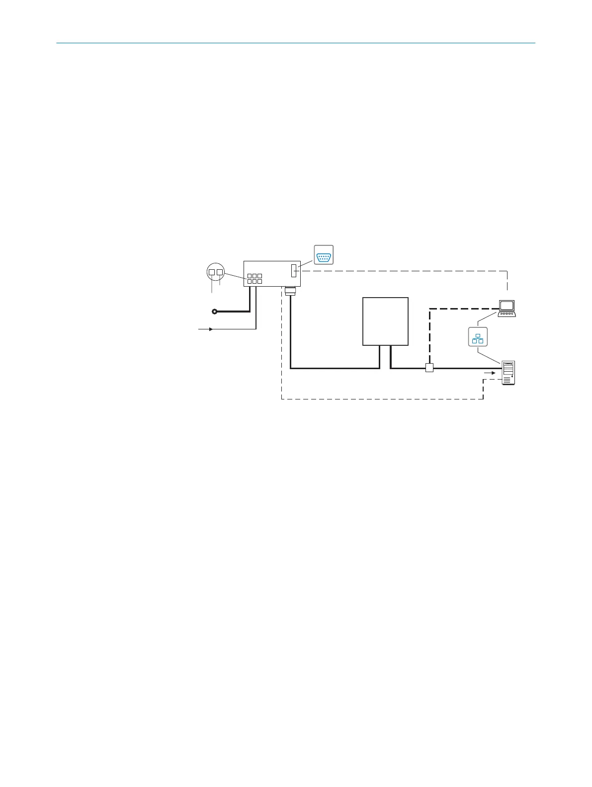
Figure 7: CLV63x to CLV65x facilities for connecting, Ethernet variant, M12, 12-pin, A-coded
1
Supply voltage V
S
(V
S
= U
V
)
2
Connection module (optional, CDB620 here as example)
3
Device
4
Null modem cable (female connector, D-Sub, 9-pin/female connector, D-Sub, 9-pin),
crossed TxD and RxD
5
Alternative to Ethernet AUX port
6
Alternative to serial AUX
7
Configuration or diagnostics
8
Read result
9
Data further processing
ß
Alternative to Ethernet host port
à
Adapter cable (male connector, M12, 4-pin, D-coded/male connector, RJ-45, 8-pin)
á
Adapter cable (female connector, M12, 12-pin, A-coded/male connector, D-Sub-HD, 15-
pin)
â
Digital switching input 1, e.g., for connecting a read cycle sensor
PRODUCT DESCRIPTION 3
8019588/129Z/2019-02-07 | SICK O P E R A T I N G I N S T R U C T I O N S | CLV63x, CLV64x, CLV65x
19
Subject to change without notice

 Loading...


