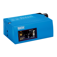
5.5 Mounting the device
NOTICE
In devices with heating:
The device must not be exposed to strong air flows (e.g. from air circulation) since the
required heat can otherwise not be output. If necessary, take appropriate measures to
shield the device from air flows.
If the device is used outside, we recommend installing it into an additional protective
housing. This prevents contamination of the reading window by rain, snow or dust. The
housing also protects from wind.
NOTICE
In devices with heating:
At an ambient temperature under 0 °C, the connecting cables, the (type-dependent)
swivel connector on the device and the configuration switch on the optional connection
module must not be moved.
NOTICE
Risk of damaging the device!
Observe the maximum screw-in depth of the blind hole thread. Longer screws than
specified damage the device.
b
Use screws of suitable length.
1. Prepare the base for mounting the bracket of the device, see "Preparation for
mounting", page 28.
2. Place the object with the bar code in the view of the device in the position where
the reading is to take place (conveyor static).
3. Align device with the bar code by eye. When doing so, be aware of the following:
– For a device with the reading window at the front, ensure that the rear side
with the laser warning label points in the direction of the observer and is
aligned as near as possible to being parallel to the bar code surface.
– For a device with the reading window at the side, ensure that the side panel
with the LEDs points in the direction of the observer and is aligned almost
parallel to the bar code surface.
– In a device with oscillating mirror, the wide side panel (rear of the oscillating
mirror) is almost parallel to the bar code surface.
– During reading, note the reading angle that occurs see "Angle alignment of
the device", page 31.
– If the position of the bar code within the scanning line is relevant for the eval‐
uation, bear in mind the count direction of the code position see "Count direc‐
tion of the reading angle and the code angle", page 33.
4. Mount the device bracket onto the base.
5. Screw screws through the bracket into the blind hole threads of the device and
slightly tighten.
6. Configure the device, see "Adjust the device", page 57.
5.6
Mounting with shock mounts (optional)
In application areas with severe vibrations or shocks caused by vibrations, jolts or
abrupt changes in directions (e.g. when mounted to a manned forklift truck), mounting
with shock mounts is to be carried out. Suitable shock mounts are available as acces‐
sories.
5 MOUNTING
34
O P E R A T I N G I N S T R U C T I O N S | CLV63x, CLV64x, CLV65x 8019588/129Z/2019-02-07 | SICK
Subject to change without notice

 Loading...