Data
output 5
Trigger 2:
Stop
reading 2
Trigger 1:
Start
reading 3
Reading field 4
Start/Stop operation 1
Figure 12: Start/stop operating mode of the device in stand-alone operation
1
Start/stop operation
2
Trigger 2: Stop reading
3
Trigger 1: Start reading
4
Reading field
5
Data output
NOTE
The SOPAS ET configuration software can be used to configure the reading operation
mode.
Alternatively, configuration can be done via GSD file (Ethernet version/PROFINET).
3.2.3.6 Tracking operation (only CLV65x-x8300A)
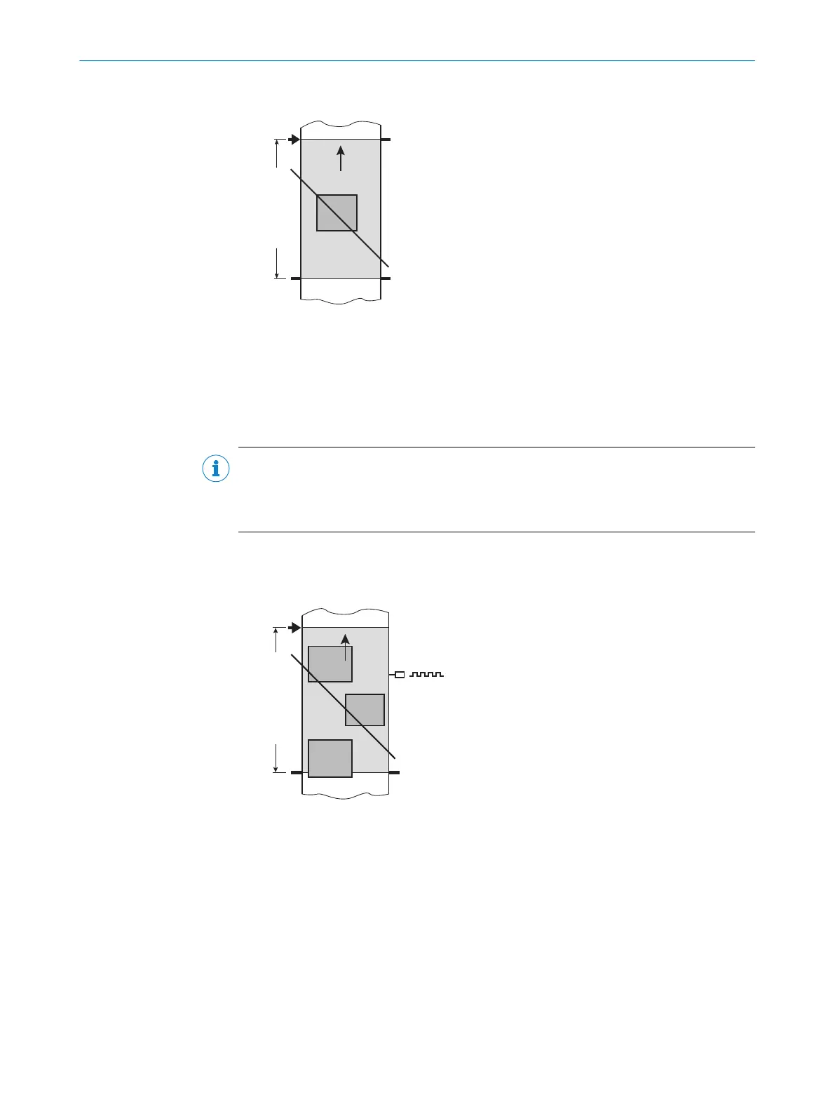
Tracking operation 1
Trigger 1:
Start 2
Reading field 3
Data
output 4
Figure 13: Tracking operating mode of the device in stand-alone operation
1
Tracking operation
2
Trigger 1: Start reading
3
Reading field
4
Data output
In the internal tracking operation, there are a maximum of 10 objects behind each
other in the reading field at the same time during the reading process.
As standard, the start of the reading process is controlled by a read cycle sensor at the
start of the reading field. The specification of the object release point defines the end.
This also defines the size of the resulting reading field.
3
PRODUCT DESCRIPTION
24
O P E R A T I N G I N S T R U C T I O N S | CLV63x, CLV64x, CLV65x 8019588/129Z/2019-02-07 | SICK
Subject to change without notice

 Loading...


