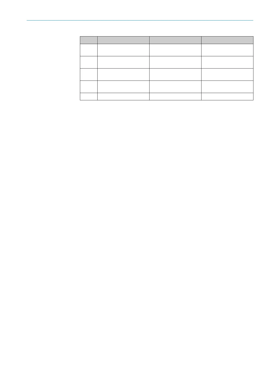
Table 5: System connection pin assignment (male connector, M12, 5-pin)
Pin Wire color
1)
s S
ender r Receiver
1 Brown +24 V DC (voltage supply
in
put)
+24 V DC (voltage supply
input)
2 White Reserved OSSD1 (output signal
switching device 1)
3 Blue 0 V DC (voltage supply
input)
0 V DC (voltage supply
input)
4 Black Reserved OSSD2 (output signal
switching device 2)
5 Gray Not connected Not connected
1)
Applies to the connecting cables recommended as accessories.
Further topics
•
"Int
egrating into the electrical control", page 19
6.3 System connection via connection cable (M12, 5-pin to 8-pin)
An optional connection cable is available to connect the 5-pin system connection to an
e
xisting 8-pin female connector. The connection cable can be used to replace an exist‐
ing M4000 multiple light beam safety device with a deTem4 Core multiple light beam
safety device, without having to route new cables.
6 ELE
CTRICAL INSTALLATION
38
O P E R A T I N G I N S T R U C T I O N S | deTem4 Core 8020453/14Q7/2020-04-27 | SICK
Subject to change without notice