Technical data for sender
T
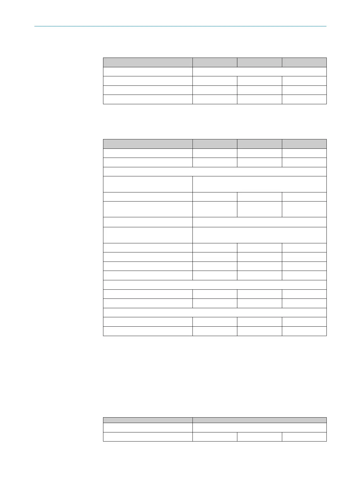
able 10: Technical data for sender
Minimum Typical Maximum
Wavelength of sender Near-infrared (NIR), invisible
Effective aperture angle (EAA)
1)
2.5°
Current consumption 50 mA
Power consumption 1.44 W
1)
Distance between sender and receiver D ≥ 3 m.
Technical data for receiver
T
able 11: Technical data for receiver
Minimum Typical Maximum
Current consumption 150 mA
Power consumption 4.32 W
Output signal switching devices (OSSDs)
Type of output 2 PNP semiconductors, short-circuit protected
1)
, cr
oss-
circuit monitored
Duration of OFF state 100 ms
Switch-on delay 3 × response
t
ime
Output voltage for ON state (HIGH)
2)
(U
V
– 2.25 V) … U
V
Output voltage for OFF state (LOW)
2)
3)
0 V … 2.0 V
Output current for ON state (HIGH) 300 mA each
Leakage current of the OSSDs 2 mA each
Load capacity 2.2 µF
Load inductance 2.2 H
Test pulse data
4)
Test pulse width 150 µs 300 µs
Test pulse rate 3 s
–1
5 s
–1
10 s
–1
Permissible cable resistance
Between device and load
5)
2.5 Ω
Supply cable
6)
1 Ω
1)
Applies to the voltage range between -30 V and +30 V.
2)
According to IEC 61131-2.
3)
The specified values are the switching voltage passed to the device. If higher voltages are impressed from
t
he outside, the maximum value of 2.0 V can be exceeded.
4)
When active, the outputs are tested cyclically (brief LOW). When selecting the downstream controllers,
make sure that the test pulses do not result in deactivation when using the above parameters.
5)
The cable resistance of the individual wires to the downstream controller must not exceed this value, to
ensure that a cross-circuit between the outputs is safely detected. (Observe standard IEC 60204-1 too.)
6)
The supply cable must not be used to connect other loads with the exception of the sender.
Operating data
T
able 12: Operating data
System connection Male connector, M12, 5-pin
Length of cable
1)
50 m
12 TECHNICAL DATA
54
O P E R A T I N G I N S T R U C T I O N S | deTem4 Core 8020453/14Q7/2020-04-27 | SICK
Subject to change without notice