Operating Instructions Chapter 3
DME4000
8014584/ZN33/2017-07 © SICK AG • Germany • Subject to change without notice 75
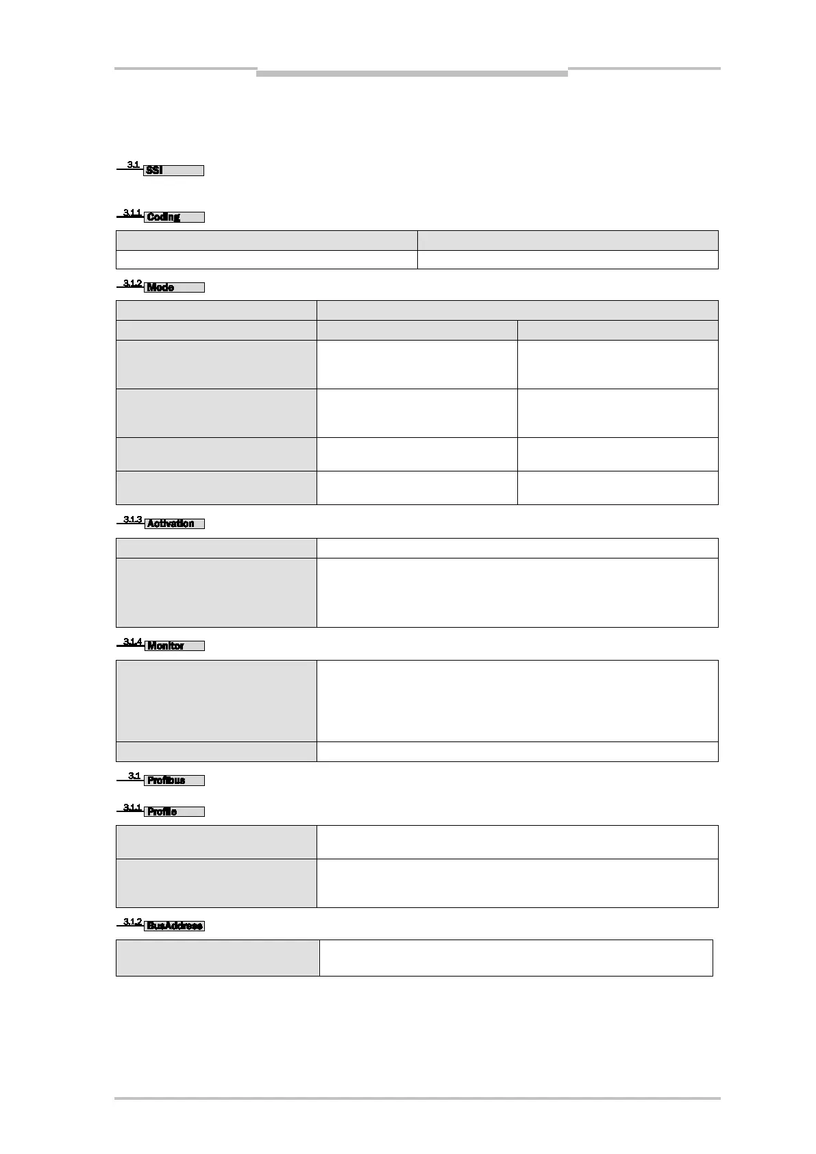
Depending on the sensor type, only the respective interface of the sensor type appears in the menu.
For the function of the SSI interface, refer to Chapter 8.2.3 “SSI“.
Measurement value output in binary code
Measurement value output in gray code
25 bit (default)
Bit 1 ... 24
LSB: Plausibility bit
Measurement value incl. plausibility bit
coded in gray code
24 bit + err
Bit 1 ... 24
LSB: Plausibility bit
Bit 1 ... 24
LSB: Plausibility bit (binary)
24 bit
Bit 0 ... 23
Bit 0 ... 23
Plausibility bit:
measurement value output 0
SSI interface in operation, RS 422 interface not in operation.
Off
RS 422 interface in operation, SSI interface not in operation. The RS 422 interface
enables parameterizing the DME with the interface adapter
(1 023 359).
(Set baud rate and protocol under > 3.2 Serial <)
On
Serial monitor interface in connection with the interface adapter (part no.
1 023 359, refer to accessories) via the MF1 and MF2. The switched on monitor
interface is displayed with “Monitor” in the menu 3.3.2 and 3.4.2 MF function. The
SSI interface is capable of performing all functions. Baud rate and protocol are set
via 3.2 Serial.
Multifunctional outputs MF1 and MF2 in operation as set under 3.3/3.4.
Encoder
This profile corresponds to the standard encoder profile; refer to “9.2 PROFIBUS
Interface”.
SICK (default)
This profile is based on the standard encoder profile. In addition to the
measurement value, warning, state and error information are transmitted.
For a more precise description, see “9.2 PROFIBUS Interface”.
Addr. 006 (default)
The Profile bus subscriber address is set here.
(001-125)
For an operation startup example with Siemens Step 7 (see Chapter 9.5 “RS-422 Interface”).