Chapter 4 Operating Instructions
DME4000
86 © SICK AG • Germany • Subject to change without notice 8014584/ZN33/2017-07
Reliable data transmission is provided with shielded lines with wires stranded in pairs. A comprehensive
shield concept that functions flawlessly is required for interference-free data transmission. Special
attention must be paid to grounding of the cable shield to the switching cabinet and the DME4000. The
cable shield of the prefabricated cable is connected with the metal plug and consequently with the
DME4000 housing. The cable shield on the switching cabinet must be connected with the system
ground over a large area. Potential compensating current via the cable shield is prevented by a suitable
ground cable. The shields of the PROFIBUS lines are connected to each other via the PROFIBUS plug.
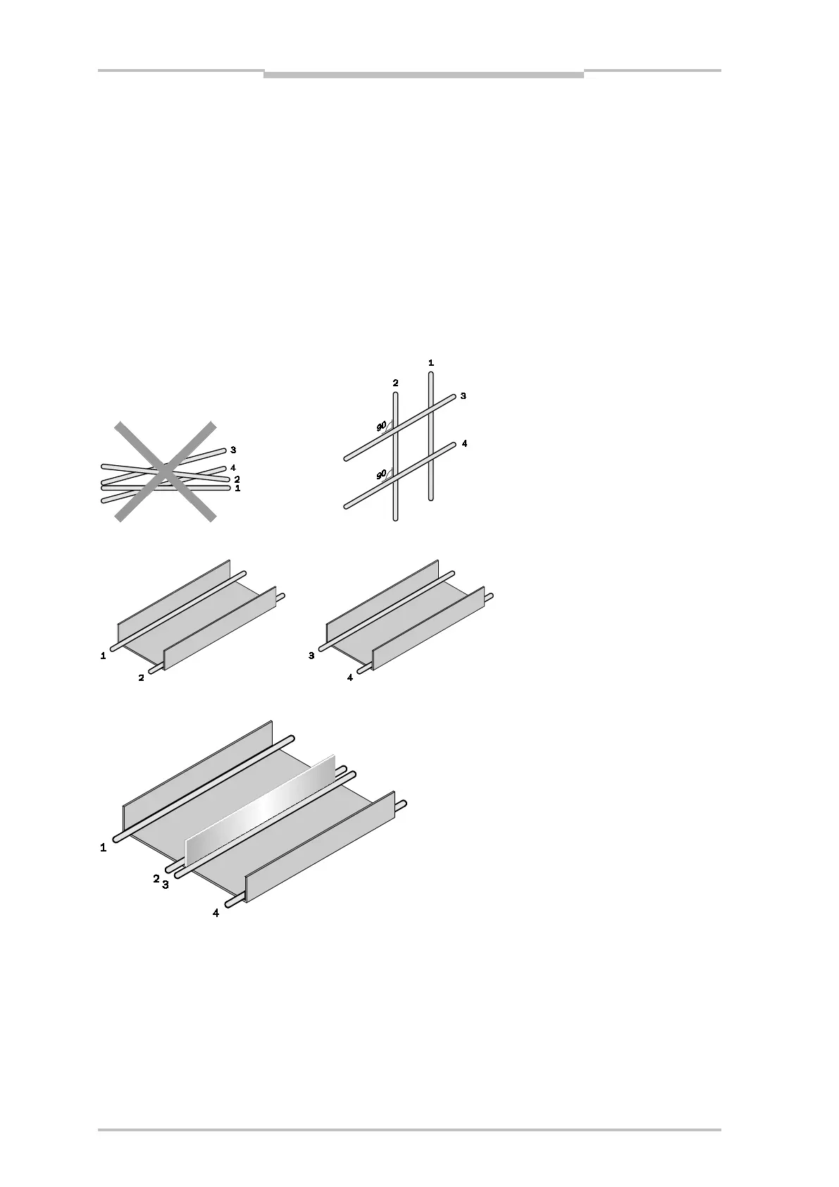
Key for cable groups Illustration 4.12 – Illustration 4.14:
1 =Line very sensitive to interference (analog measurement lines)
2 =Interference-sensitive lines (sensor cables, communication signals, bus lines)
3 =Interference-source lines (control cable for inductive loads, engine brakes)
4 =Lines causing strong interference (outlet cable of frequency convertor, power supply to welding
systems, electric power cable)
Illustration 4.12 – Cross the lines of groups 1 and 2 with 3 and 4 at right angles
Illustration 4.13 – Ideally: lay lines in different cable ducts
Illustration 4.14 – Alternatively: separate lines by metal rib