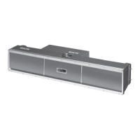
Operating Instructions
ICR890
Figures and tables
8011325/0000/2006-10-24 © SICK AG · Division Auto Ident · Germany · All rights reserved 11
Tables
Tab. 1-1: Target audience ................................................................................................ 15
Tab. 3-1: Included in the delivery of the ICR890 High-end CCD Camera System ........ 25
Tab. 3-2: System component versions............................................................................ 26
Tab. 3-3: General system requirements (standard device) ........................................... 27
Tab. 3-4: Data interface function..................................................................................... 39
Tab. 3-5: LED indications ................................................................................................. 42
Tab. 5-1: ICR890 System (stand-alone device) without MSC800: Overview of
the ICD890 Camera connections which have to be established .................. 55
Tab. 5-2: ICR890 System (stand-alone device) with MSC800: Overview of
the ICD890 Camera connections which have to be established .................. 56
Tab. 5-3: ICR890 System (stand-alone device) with MSC800: Overview of
the MSC800 connections which have to be established............................... 57
Tab. 5-4: ICR890 System with MSC800 (multi-side reading): Overview of
the ICD890 Camera connections which have to be established .................. 58
Tab. 5-5: ICR890 System with MSC800 (multi-side reading): Overview of
the MSC800 connections which have to be established............................... 59
Tab. 5-6: ICR890 System with MSC800 (multi-side reading): Overview of
the VMS4xx/5xx connections which have to be established......................... 59
Tab. 5-7: ICD890 Camera: Function of the electrical connections ............................... 61
Tab. 5-8: ICI890 Illumination: Function of the electrical connections .......................... 61
Tab. 5-9: MSC800-0000 logic controller: Function of the electrical
connections (overview)..................................................................................... 62
Tab. 5-10: Cables for connecting the ICR890 System ..................................................... 63
Tab. 5-11: Maximum cable lengths between ICR890 and the host................................ 65
Tab. 5-12: CAN bus: Maximum cable lengths, depending on the data transfer rate..... 66
Tab. 5-13: CAN bus: Maximum stub cable lengths, depending on the data
transfer rate ...................................................................................................... 66
Tab. 5-14: CAN bus: Required wire cross section, depending on the data
cable length....................................................................................................... 67
Tab. 5-15: Ratings of the switching inputs IN1 and IN 2 ................................................. 69
Tab. 5-16: Ratings of the switching outputs Result 1 and Result 2................................ 70
Tab. 5-17: ICD890 Camera: Pin assignment of the 8-pole RJ-45 sockets
“GBIT1“ and “GBIT2“........................................................................................ 71
Tab. 5-18: ICD890 Camera: Pin assignment of the 5-pole M12 sockets
“CAN 1-OUT“/“CAN 2-OUT“ .............................................................................. 71
Tab. 5-19: ICD890 Camera: Pin assignment of the 5-pole M12 plugs
“CAN 1-IN“/“CAN 2-IN“..................................................................................... 72
Tab. 5-20: ICD890 Camera: Pin assignment of the 8-pole M12
socket “ILLUMINATION“.................................................................................... 72
Tab. 5-21: ICD890 Camera: Pin assignment of the 8-pole M12 plug “AUX“ .................. 72
Tab. 5-22: ICD890 Camera: Pin assignment of the 8-pole M12 plug “HOST“ ............... 72
Tab. 5-23: ICD890 Camera: Pin assignment of the 4-pole M12 plug “OUT“.................. 73
Tab. 5-24: ICD890 Camera: Pin assignment of the 5-pole M12 socket “IN 1“.............. 73
Tab. 5-25: ICD890 Camera: Pin assignment of the 5-pole M12 socket “IN 2“.............. 73
Tab. 5-26: ICD890 Camera: Pin assignment of the 4-pole M12 socket
“HOST ETHERNET“............................................................................................ 73
Tab. 5-27: ICD890 Camera: Pin assignment of the 8-pole Harting HanQ8 plug
“POWER IN“....................................................................................................... 74
Tab. 5-28: ICD890 Camera: Pin assignment of the 8-pole Harting HanQ8 socket
“POWER OUT“.................................................................................................... 74
Tab. 5-29: ICI890 Illumination: Pin assignment of the 8-pole Harting HanQ8 plug
“POWER IN“....................................................................................................... 75
Tab. 5-30: ICI890 Illumination: Pin assignment of the 8-pole M12 plug
“ILLUMINATION“................................................................................................ 75
Tab. 5-31: Wire colours assignment: Cable no. 6028420 (HOST/AUX), standard ........ 75
Tab. 5-32: Wire colours assignment: Cables no. 6021166/no. 6021175

 Loading...