Chapter 5 Operating Instructions
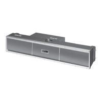
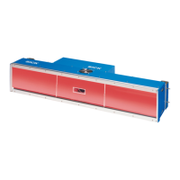
ICR890 High-end CCD Camera System
72 © SICK AG · Division Auto Ident · Germany · All rights reserved 8011325/0000/2006-10-24
Electrical installation
“CAN 1-IN“/“CAN 2-IN“ connections (CAN-SENSOR networks)
-
“ILLUMINATION“ connection (control data interface for illumination)
“AUX“ connection (auxiliary data interface)
“HOST“ connection (main data interface)
Pin CAN signal Function
1 Shield Shielding
2 CAN_V+ Supply voltage 24 V
3CAN_GND Ground
4 CAN_H CAN bus (IN/OUT)
5 CAN_L CAN bus (IN/OUT)
Tab. 5-19: ICD890 Camera: Pin assignment of the 5-pole M12 plugs “CAN 1-IN“/“CAN 2-IN“
Pin Signal Function
1n. c. –
2 LAMP_ON+ Illumination ON/OFF
3n. c. –
4n. c. –
5 RD+/TD+ (RS 485) Transmitter+/Receiver+
6 RD–/TD– (RS 485) Transmitter–/Receiver–
7GND Ground
8n. c. –
Tab. 5-20: ICD890 Camera: Pin assignment of the 8-pole M12 socket “ILLUMINATION“
Pin Signal Function
1n. c. –
2n. c. –
3 RD+ (RS 485) Receiver+
4 RD–/RxD (RS 485/RS 232) Receiver–/Receiver
5 TD+ (RS 485) Transmitter+
6 TD–/TxD (RS 485/RS 232) Transmitter–/Transmitter
7GND Ground
8 Shield Shielding
Tab. 5-21: ICD890 Camera: Pin assignment of the 8-pole M12 plug “AUX“
Pin Signal Function
1n. c. –
2n. c. –
3 RD+ (RS 485) Receiver+
4 RD–/RxD (RS 485/RS 232) Receiver–/Receiver
5 TD+ (RS 485) Transmitter+
6 TD–/TxD (RS 485/RS 232) Transmitter–/Transmitter
7GND Ground
8 Shield Shielding
Tab. 5-22: ICD890 Camera: Pin assignment of the 8-pole M12 plug “HOST“