Operating Instructions Chapter 5
ICR890
Electrical installation
8011325/0000/2006-10-24 © SICK AG · Division Auto Ident · Germany · All rights reserved 71
5.5 Pin assignments and conductor colouring assignment
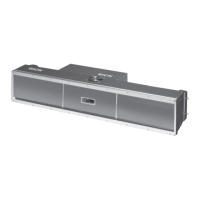
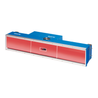
5.5.1 ICD890 Camera connections
Note All connections have been provided with protective caps for delivery.
“GBIT 1“/“GBIT 2“ connections (Ethernet, max. 1GBps)
-
“CAN 1-OUT“/“CAN 2-OUT“ connections (CAN-SENSOR networks)
-
Abb. 5-10: ICD890 Camera: Electrical connections (standard system)
Ethernet
(GBit channels)
Power supply
Ethernet
(host)
Pin Ethernet signal Function
1 TD+ Transmitter+
2 TD– Transmitter–
3RD+ Receiver+
4n. c. –
5n. c. –
6RD– Receiver–
7n. c. –
8n. c. –
Tab. 5-17: ICD890 Camera: Pin assignment of the 8-pole RJ-45 sockets “GBIT1“ and “GBIT2“
Pin CAN signal Function
1 Shield Shielding
2 CAN_V+ Supply voltage 24 V
3CAN_GND Ground
4 CAN_H CAN bus (IN/OUT)
5 CAN_L CAN bus (IN/OUT)
Tab. 5-18: ICD890 Camera: Pin assignment of the 5-pole M12 sockets “CAN 1-OUT“/“CAN 2-OUT“