Operating Instructions Chapter 5
ICR890
Electrical installation
8011325/0000/2006-10-24 © SICK AG · Division Auto Ident · Germany · All rights reserved 61
The following interfaces are realized via the ICD890 Camera connections:
-
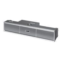
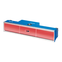
5.3.2 Electrical connections of the ICI890 Illumination
The ICI890 Illumination is equipped with a Harting connector for the power supply and an
M12 connector for the control line.
The following interfaces are realized via the ICI890 Illumination connections:
-
Connection Design Number of
poles
Function
GBIT 1 ETHERNET RJ-45 8, socket Image data output, channel 1
GBIT 2 ETHERNET RJ-45 8, socket Image data output, channel 2
CAN 1-OUT M-12 5, socket Output CAN-SENSOR network 1
CAN 1-IN M-12 5, plug Input CAN-SENSOR network 1
CAN 2-OUT M-12 5, socket Output CAN-SENSOR network 2 (reserved)
CAN 2-IN M-12 5, plug Input CAN-SENSOR network 2 (reserved)
ILLUMINATION M-12 8, socket Control data interface ICI890 Illumination
AUX M-12 8, plug
Auxiliary data interface
(RS 232, RS 422/485)
HOST M-12 8, plug Main data interface (RS 232, RS 422/485)
OUT M-12 4, plug Two digital switching outputs (system status)
IN 1 M-12 5, socket Digital switching input (reading pulse)
IN 2 M-12 5, socket Digital switching input (reading pulse, increment)
HOST ETHERNET M-12 5, socket Main data interface (10/100 MBps)
POWER IN Harting
HanQ8
8, plug Power supply input 24 V DC
POWER OUT Harting
HanQ8
8, socket Output 24 V DC, to ICI890 Illumination
Tab. 5-7: ICD890 Camera: Function of the electrical connections
Design Number of
poles
Function
M-12 8, plug Control data interface ICD890 Camera
Harting
HanQ8
8, plug Power supply input 24 V DC
Tab. 5-8: ICI890 Illumination: Function of the electrical connections