Operating Instructions
ICR890
Figures and tables
8011325/0000/2006-10-24 © SICK AG · Division Auto Ident · Germany · All rights reserved 13
Figures
Fig. 2-1: LED radiation outlet opening ........................................................................... 19
Fig. 3-1: ICR890 System in combination with the MSC800 (single-side reading)...... 23
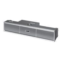
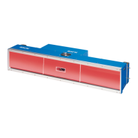
Fig. 3-2: View of the ICD890 camera and the ICI890 Illumination.............................. 24
Fig. 3-3: Work area of the ICR890 System (standard device)...................................... 26
Fig. 3-4: Example of simple system installation on the installation frame.................. 27
Fig. 3-5: The ICR890 System at a conveyor system, single-side reading from above 31
Fig. 3-6: System diagram for single-side reading from above...................................... 32
Fig. 3-7: Diagram of the illumination with illuminated area ......................................... 33
Fig. 3-8: ICR890 System with deflection mirror for reading from above..................... 34
Fig. 3-9: Position of the ICR890 System and the tilt angle........................................... 35
Fig. 3-10: Example of an image recording for analysis ................................................... 36
Fig. 3-11: Image analysis (blue rectangle: Regions of interest; green rectangle:
Successful decoding; green line: Decoder runtime at end of the
reading pulse) ................................................................................................... 36
Fig. 3-12: Reading operation modi of the ICR890 System in stand-alone operation... 38
Fig. 3-13: SD memory card for parameter set ................................................................. 41
Fig. 3-14: LEDs at the ICD890 Camera............................................................................ 42
Fig. 3-15: Pixel resolution across the direction of transport (standard device,
135 mm (5.32 in) lens) .................................................................................... 43
Fig. 3-16: Line resolution in the direction of transport (standard device,
8,192 pixels CCD sensor)................................................................................. 43
Abb. 4-1: Example of a project-specific dimensional sheet for installation.................. 46
Abb. 4-2: Free space required for connecting the camera and the illumination.......... 47
Abb. 4-3: Arrangement above the conveyor system for single-side reading
from above ........................................................................................................ 47
Abb. 4-4: Arrangement at the conveyor system for multi-side reading with
VMS4xx/5xx....................................................................................................... 48
Abb. 4-5: Arrangement at the conveyor system.............................................................. 48
Abb. 4-6: Position of the components ............................................................................. 49
Abb. 4-7: 180° bracket for the deflection mirror and the illumination......................... 49
Abb. 4-8: Removeable protective camera caps.............................................................. 51
Abb. 4-9: Position of the external components............................................................... 51
Abb. 5-1: Block diagram: connection principle of the ICR890 (standard system) ....... 54
Abb. 5-2: Block diagram: Connection principle of a ICR890 (standard system)
with MSC800..................................................................................................... 56
Abb. 5-3: Block diagram: Connection principle of several ICR890
(standard systems) with MSC800 ................................................................... 58
Abb. 5-4: ICD890 Camera: Position of the electrical connections
(standard system) ............................................................................................. 60
Abb. 5-5: MSC800-0000 logic controller: Position of the electrical connections ........ 62
Abb. 5-6: ICD890 Camera: Wiring of the HOST/AUX data interfaces............................ 66
Abb. 5-7: Block diagram: Function of the Ethernet interface......................................... 68
Abb. 5-8: Wiring of the switching inputs IN 1 and IN 2................................................... 69
Abb. 5-9: Wiring of the switching outputs Result 1 and Result 2.................................. 70
Abb. 5-10: ICD890 Camera: Electrical connections (standard system).......................... 71
Abb. 6-1: Configuration with SOPAS-ET ........................................................................... 80
Abb. 7-1: Cleaning the front window................................................................................ 90
Abb. 7-2: Cleaning the air inlet and outlet openings at the system's
illumination ICR890.......................................................................................... 90
Abb. 7-3: Cleaning of the external optical sensors (reading pulse generator,
detector for object distance)............................................................................ 92
Abb. 7-4: 180° bracket: Loosening clamping screws .................................................... 93
Abb. 7-5: ICD890 Camera: Position of the battery on the internal PC card.................. 95
Abb. 9-1: Reading areas of the ICR890 System (standard).........................................106
Abb. 9-2: Pixel resolution across the direction of transport (standard device,
135 mm (5.32 in) lens) ..................................................................................107
 Loading...