NOTE
Assign the functions for the digital inputs in the device using a configuration tool, e.g.,
the configuration software SOPAS ET.
13.2.8 Wiring the external digital inputs of the device in the CDB650-204
Device = Lector63x = V2D63xx-xxxxB
Device 4CDB650-204
PNP sensor 7
V
S
GND
3.32 K
6.64 K
18
SGND
8
Shield
11
U
IN
*
A
Out
GND
S3
E.g. photo-electric
switch 6
Trigger sensor 1
CMC600 3
U
IN
*
AUX
(RS-232)
ON
OFF
S3 : SGND-GND
No
YES
S4 : CMC
V
in
“External
input C” 5
SensGND
EXT. IN B
8
2
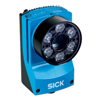
Figure 26: Trigger sensor supplied with power by connection module CDB650-204.
1
Trigger sensor
2
Input voltage V
in
3
The optional CMC600 parameter cloning module is required in the connection module in order to use the additional
external digital inputs and digital outputs of the device.
4
Device
5
Logical “External input” in the device
6
E.g. photoelectric sensor
7
PNP sensor
8
Supply voltage V
S
CDB650-204
18 SGND
8 Shield
11
U
IN
*
A
GND
S3
U
IN
*
CMC600
ON
OFF
S3 : SGND-GND
No
YES
S4 : CMC
V
in
SensGND
1
V
S ext
GND
A
18
2
EXT. IN B
CDB650-204
PNP sensor 4
V
S
GND
18
SGND
8
Shield
11 U
IN
*
A
Out
GND
S3
V
S ext
CMC600
U
IN
*
No
YES
S4 : CMC
ON
OFF
S3 : SGND-GND
V
in
SensGND
Trigger sensor 1
EXT. IN B
2
5
2
3 3
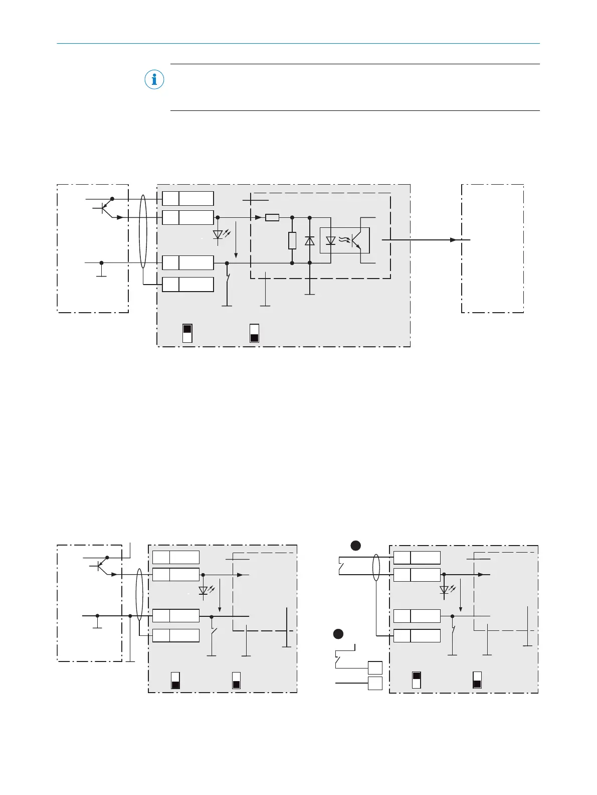
Figure 27: Left: Trigger sensor connected potential-free and supplied with power externally. Right: Alternatively switch,
!
supplied with power by connection module CDB650-204 or
"
connected potential-free and supplied with power externally.
Switch setting S3 then as in left figure.
13 ANNEX
78
O P E R A T I N G I N S T R U C T I O N S | Lector63x Flex C-mount and S-mount 8018071/1E1C/2021-12-16 | SICK
Subject to change without notice