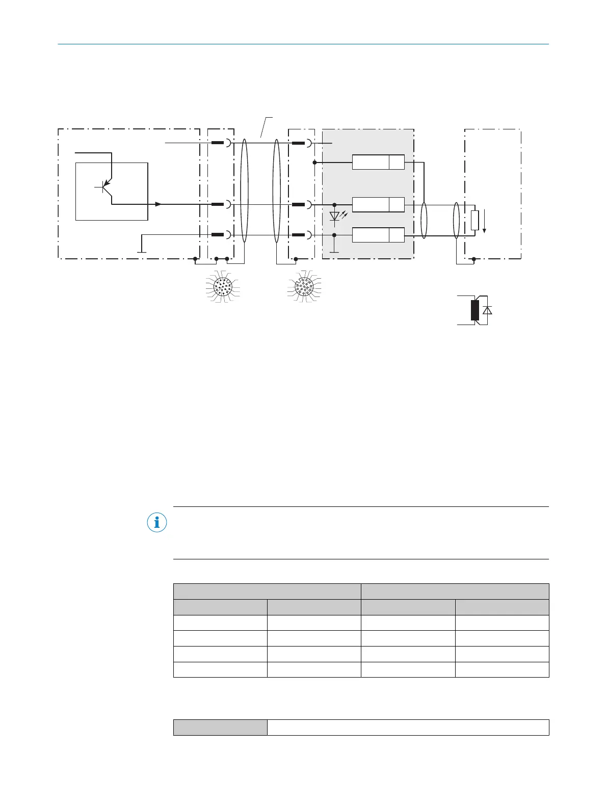
13.2.9 Wiring digital outputs of the device in the CDB650-204
Device = Lector63x = V2D63xx-xxxxBx
Device 1
CDB650-204
Load (e.g. PLC) 4
Cable 3
B
1
.
.
.
D
22
GND
5Shield
U
IN
*V
S
GND
V
out
Result A
GND
B
1
2
2
For inductive load: 6
3
1
7
2
6
5
4
8
13
14
17
15
9
10
12
16
11
3
1
7
2
6
5
4
8
13
14
17
15
9
10
12
16
11
RES/OUT C
8 7
2
5
Figure 28: Wire the digital output in the CDB650-204 connection module.
1
Device
2
Supply voltage V
S
3
Connection cable 1:1 (female connector, M12, 17-pin, A-coded/male connector, M12, 17-pin, A-coded)
4
Load (e.g. PLC)
5
Output voltage V
out
6
With inductive load: see note
7
Connection module: female connector, M12, 17-pin, A-coded
8
Device: male connector, M12, 17-pin, A-coded
Inductive load
NOTE
Provide an arc-suppression switch at the digital output if inductive load is present.
b
Attach a freewheeling diode directly to the load for this purpose.
Table 26: Assignment of placeholders to the digital outputs
Device CDB650-204
Output A Pin B Signal C Terminal D
Result 1 13 RES/OUT 1 20
Result 2 14 RES/OUT 2 21
Result 3 16 RES/OUT 3 50
Result 4 17 RES/OUT 4 51
Characteristic data of the digital outputs
Table 27: Characteristic data of the digital switching outputs
Type Switching
13 ANNEX
80
O P E R A T I N G I N S T R U C T I O N S | Lector63x Flex C-mount and S-mount 8018071/1E1C/2021-12-16 | SICK
Subject to change without notice