„V
S
”
“Host 1”
“Aux 1”
“Result 2”
“Result 1”
“CAN”
“Sensor 2”
“Sensor 1”
“AUX”
CAN bus
“Result 1”
“Result 2”
PLC
“External output 2
CDM420-0006
Connection module 6
“Host 1”
“Aux 1”
RS-232
HOST/PLC
Further data
processing 8
Computer
Configuration
Diagnostics
Image display
Interfaces 3
Device 2
“Ethernet” (Host 2/Aux 2), Image transfer 5
“USB” (Aux 3) 4, Image transfer 5
RS-232/RS-422
Ethernet
USB
“Host 2”
Ethernet
“Aux 2”
“Aux 3”
“Sensor 2”
“Sensor 1”
“External input 2”
“External input 1”
CMC600
1
ã
â
V
S
ß
= á
“External output 1”
à 9
7
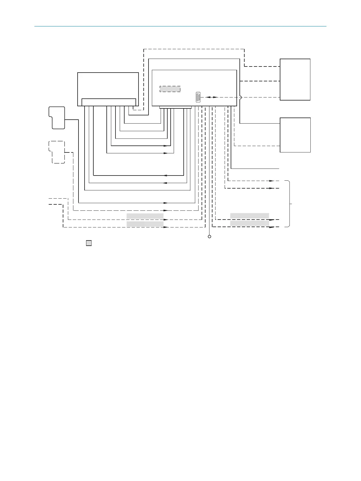
Figure 30: Connection of the device (Ethernet variant) to peripherals via CDM420-0006 (overview).
1
External trigger sensor
2
Device
3
Interfaces
4
USB interface, for temporary use as a servicing interface only
5
Image transmission
6
Connection modules
7
Configuration, diagnostics or image display
8
Data further processing
9
External digital outputs
ß
Supply voltage V
S
à
External digital inputs
á
The optional CMC600 parameter cloning module is required in the connection module in order to use the additional
external digital inputs and outputs of the device (highlighted in gray).
â
Other functions
ã
Application-dependent alternative stop trigger (e.g., photoelectric sensor) or travel increment (incremental encoder)
13.3.2 Wiring overview of the CDM420-0006
Device = Lector63x = V2D63xx-xxxxBx
ANNEX 13
8018071/1E1C/2021-12-16 | SICK O P E R A T I N G I N S T R U C T I O N S | Lector63x Flex C-mount and S-mount
83
Subject to change without notice