3
CMC600 parameter cloning module (optional)
4
Auxiliary interface “AUX”
5
Male connector, D-Sub, 9-pin
6
Name of the digital output
7
E.g., PLC (programmable logic controller)
8
SCANNER = Device
9
Female connector, D-Sub-HD, 15-pin
ß
Device to be connected
à
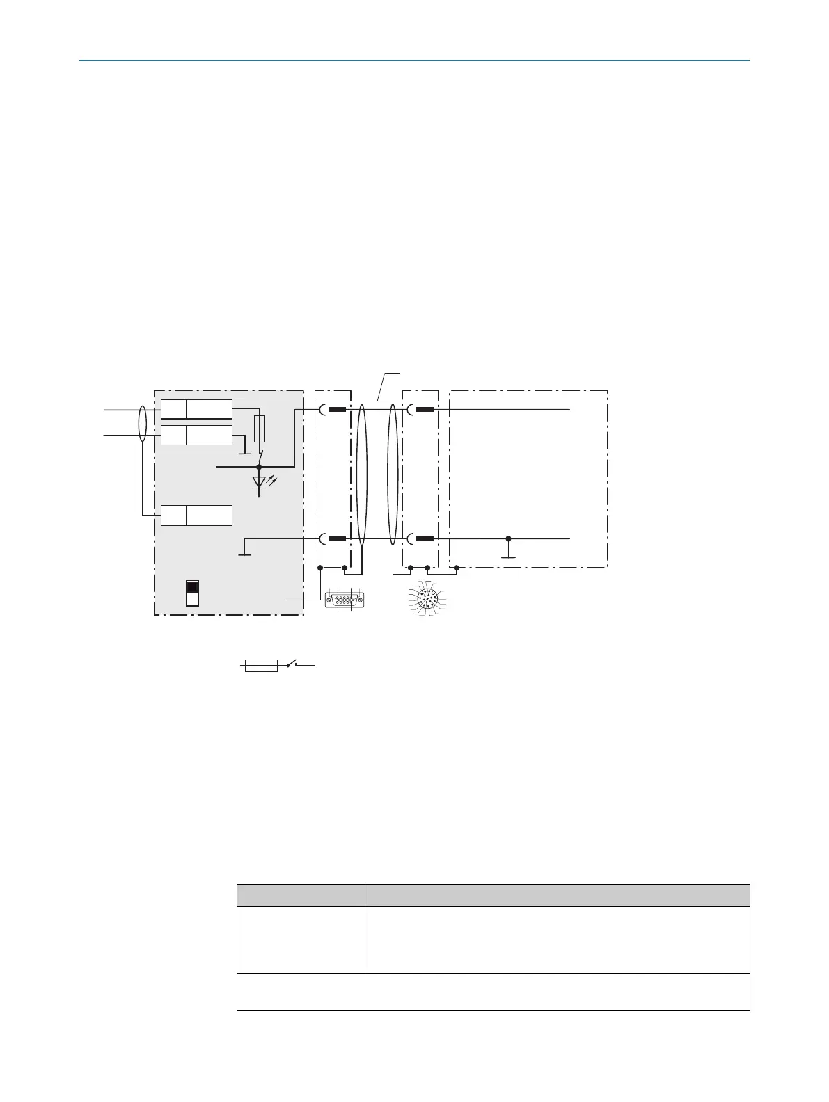
The optional CMC600 parameter cloning module is required in the connection module in order to use the additional
external digital inputs and outputs of the device (highlighted in gray).
13.3.3 Connecting supply voltage for the device in CDM420-0006
Device = Lector63x = V2D63xx-xxxxBx
Device
3CDM420-0006
V
S
2
1
1
5
5
Shield
1 +24 V
2 GND
+24 V*
GND
S1
F
Shield
GND
.
.
.
.
.
.
.
.
.
ON
OFF
S1 : POWER
+24 V*
POWER
V
S
GND
3
1
7
2
6
5
4
8
13
14
17
15
9
10
12
16
11
V
S
- +24 V -
F
S 1
- +24 V*
5 4
Cable 2
V
s
1
110
15
6
11
5
Figure 32: Connecting supply voltage for the device in CDM420-0006 connection module.
1
Supply voltage V
S
2
Adapter cable (male connector, D-Sub-HD, 15-pin / female connector, M12, 17-pin, A-coded)
3
Device
4
Device: male connector, M12, 17-pin, A-coded
5
Connection module: female connector, D-Sub-HD, 15-pin
Function of switch S1
Table 30: Switch S1: Power
Switch setting Function
ON Supply voltage +24 V connected to CDM420-0006 and device via fuse
as +24 V* supply voltage
Supply voltage +24 V* can be additionally tapped at terminals 29 and
39
OFF CDM420-0006 and device disconnected from supply voltage
Recommended setting for all connection work
ANNEX 13
8018071/1E1C/2021-12-16 | SICK O P E R A T I N G I N S T R U C T I O N S | Lector63x Flex C-mount and S-mount
85
Subject to change without notice