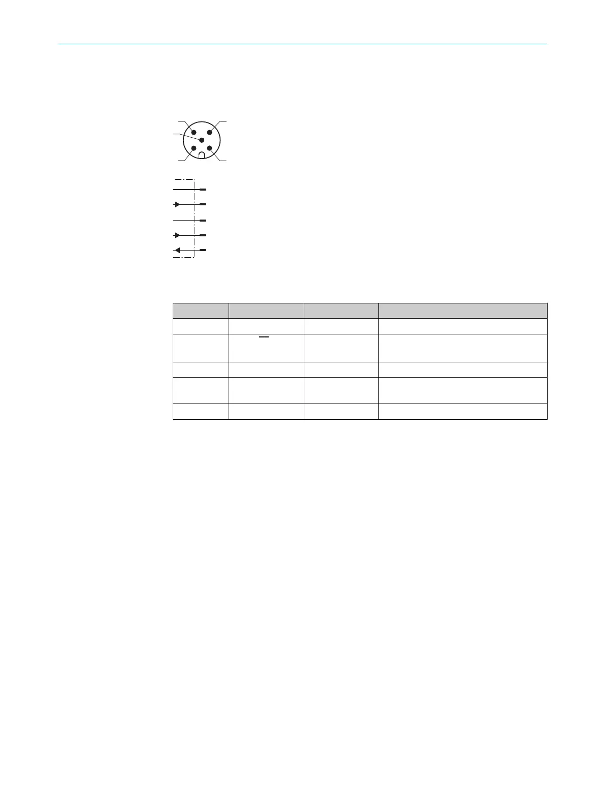
1. Ensure that the voltage supply is not connected.
2. Connect the device according to the connection diagram.
3. Observe the wiring instructions, see "Wiring notes", page 16.
L+
1
brn
M
3
blu
Q1/C
4
blk
QA/Q2/
¯
Q1
2
wht
In1
5
gra
Figure 9: Connection diagram, 5-pin male connector
Table 2: Legend for connection diagram
Contact Identification Wire color Description
1 L+ Brown Supply voltage: +18 ... +30 V DC
2 Q
A
/Q
2
/Q
1
White Output 2: analog output / switching out‐
put 2 (push-pull stage) / Q
1
not
3 M Blue Supply voltage: 0 V
4 Q
1
/C Black Output 1: switching output 1 (push-pull
stage) / IO-Link
5 In1 Gray Input 1
ELECTRICAL INSTALLATION 6
8019642/ZJW1/2017-04-03 | SICK O P E R A T I N G I N S T R U C T I O N S | OD1000
19
Subject to change without notice