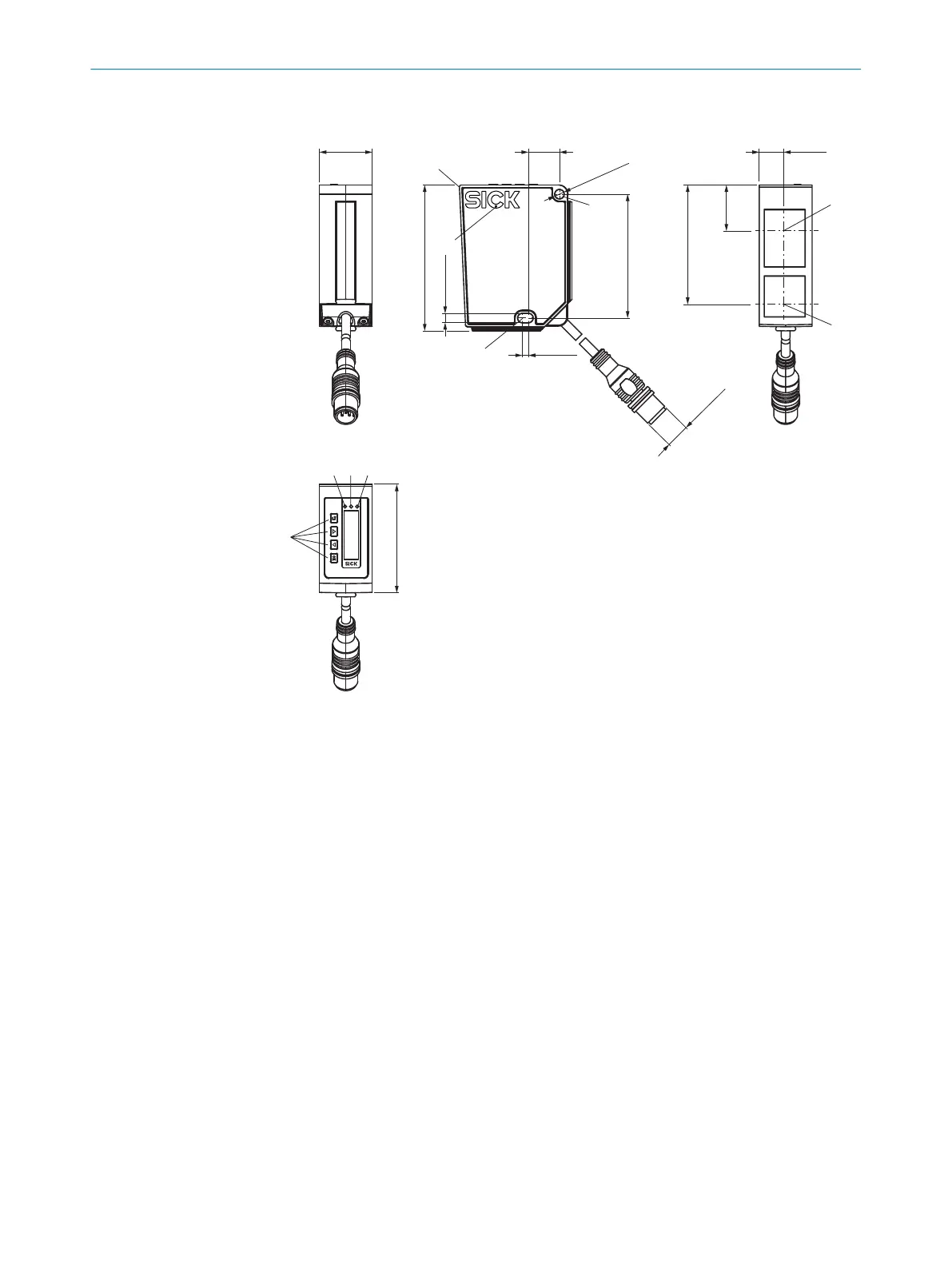
3.2 Setup and dimensions
71.5 (2.81)
60.7 (2.39)
58.55 (2.31)
22.5
(0.89)
53.2 (2.09)
11.95
(0.47)
∅ 4.5 (0.18)
4.5 (0.18)
3 (0.12)
15.2
(0.60)
PWR
Q1
Q2
M12 x 1
2
1
6
9
78
4
5
2
25.9
(1.02)
3
Figure 2: Setup and dimensions
1
Device zero point (distance = 0 mm)
2
Fixing holes (for M4)
3
Ventilation opening – do not cover!
4
Center of optical axis, receiver
5
Center of optical axis, sender
6
Display LED, green
7
Display LED, yellow
8
Display LED, yellow
9
Display operating elements
3.3 Product ID
Type label
The following information can be read off the device from the type label:
3 PRODUCT DESCRIPTION
12
O P E R A T I N G I N S T R U C T I O N S | OD1000 8019642/ZJW1/2017-04-03 | SICK
Subject to change without notice