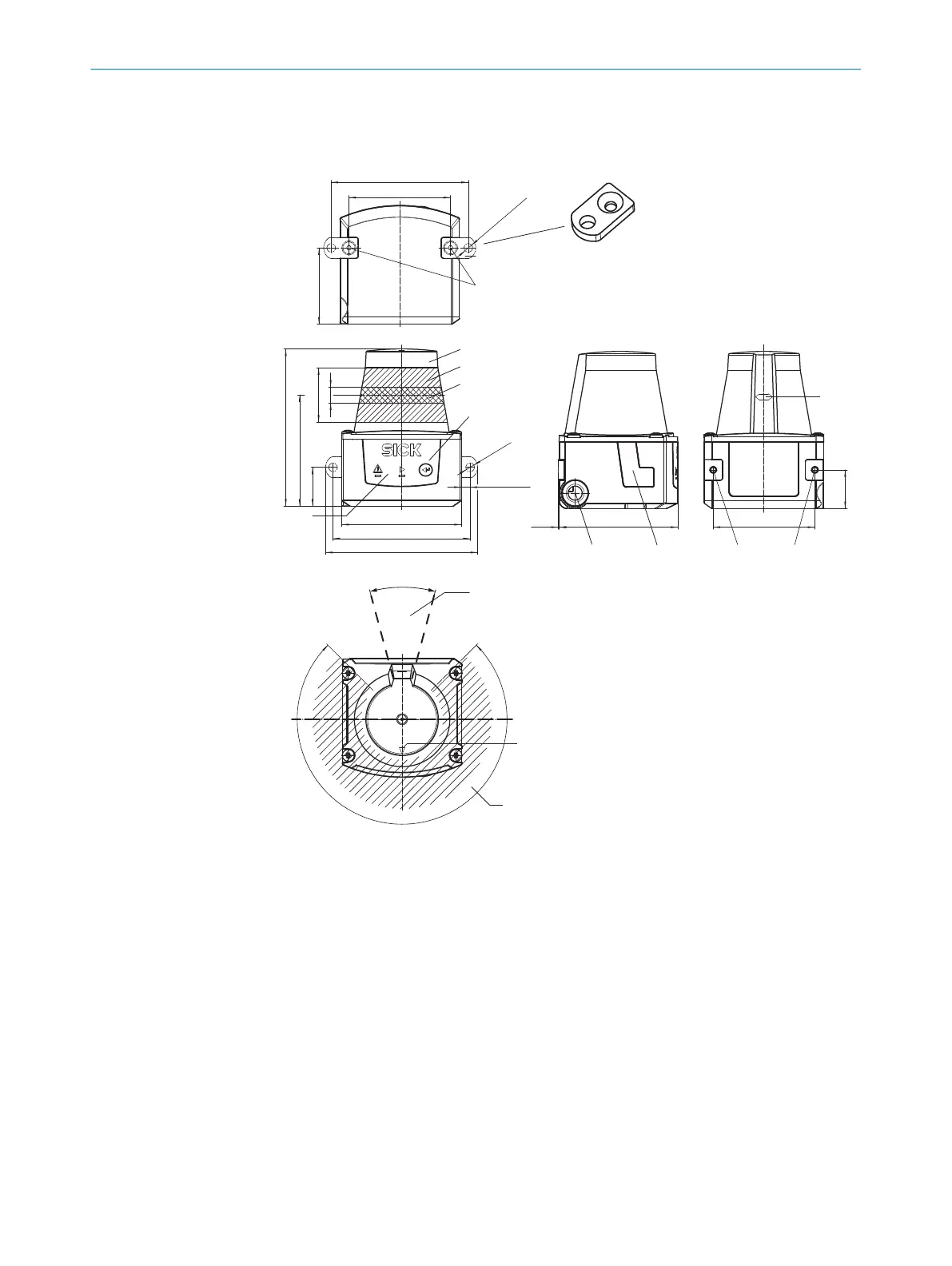
3.2 Setup and dimensions
TiM31x, TiM32x
79 (3.11)
55.8 (2.19)
60 (2.36)
8 (0.31)
27.3 (1.08)
4.4 (0.17)
(0.76)]
[19.4
4
5
3
6
7
[76.3 (3.0)]
[Ø 4.3
(0.16)
]
[68.8 (2.71)]
51 (20)
[68.8 (2.71)]
38.3 (1.50)
[Ø 4.3 (0.17)]
2
1
225°‒45°
180°0°
90°
á
à
19.4
(0.76)
51 (2.00)
[0.5
98
ß
2 2
60 (2.36)
(0.02)]
2 x
30°
â
Figure 1: Structure and dimensions, unit: mm (inch), decimal separator: period
1
2x fastening clip with M3 x 5 mm countersunk screw, self-locking (included in scope of
delivery)
2
M3 threaded mounting hole, 2.8 mm deep (blind hole thread), max. tightening torque
0.8 Nm
3
Optics cover
4
Receiving range (light inlet)
5
Transmission range (light emission)
6
Red and green LED (status indicators)
7
Function button for teach-in
8
Connecting cable outlet 0.9 m with 15-pin D-Sub HD male connector or connecting cable
0.8 m with 12-pin M12 plug ('Power/Switching inputs/outputs' connection).
9
Micro USB socket, behind the black plastic cover (“Aux interface” connection for configu‐
ration with PC)
ß
Marking for the position of the light emission level
à
Bearing marking to support alignment (90° axis)
PRODUCT DESCRIPTION 3
8024851//2021-07-21 | SICK O P E R A T I N G I N S T R U C T I O N S | TiM3xx
11
Subject to change without notice