6.2 Electrical block diagram for commissioning
TiMxxx-01xxxxx
SOPASSOPAS
"Power/I/O"
"USB 2.0"
Configuration
Field monitoring
Diagnosis
3
Device 2
Connection box 4
V
s
5
Customer-provided 1
OUT 1 OUT 2 OUT 3
IN 1 IN 2 IN 3 IN 4 PNP:
INGND
NPN:
V
s
OUT 4
USBUSB
Delay-
action
fuse
0.8 A
6
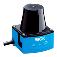
Figure 23: "Power, I/O" connection: Cable with open end
1
Connection modules
2
Device
3
Configuration, field monitoring or diagnostics
4
Supply voltage V
s
TiMxxx-10xxxxx
CDB730-001
Connection
module
1
1
2
V
s
4
GND
...
...
SOPASSOPAS
"Power/I/O"
"USB 2.0"
Configuration
Field monitoring
Diagnosis
3
Device 2
OUT 1
OUT 2
OUT 3
OUT 4
GND
22
OUT 1
20
OUT 2
21
OUT 3
10
OUT 4
13
IN 1
IN 2
IN 3
IN 4
33
43
30
SGND
12
31
USBUSB
6 1 105
11 15
Figure 24: “Power, I/O” connection: Cable with male connector, D-Sub-HD, 15-pin
1
Connection modules
2
Device
3
Configuration, field monitoring or diagnostics
4
Supply voltage V
s
TiMxxx-11xxxxx
SOPASSOPAS
"Power/I/O"
"USB 2.0"
Configuration
Field monitoring
Diagnosis
3
Device 2
Connection box 4
Customer-provided 1
OUT 1 OUT 2 OUT 3
IN 1 IN 2 IN 3 IN 4 PNP:
INGND
NPN:
V
s
OUT 4
USBUSB
Delay-
action
fuse
0.8 A
6
V
s
5
3
1
7
2
6
5
4
8
9
10
12
11
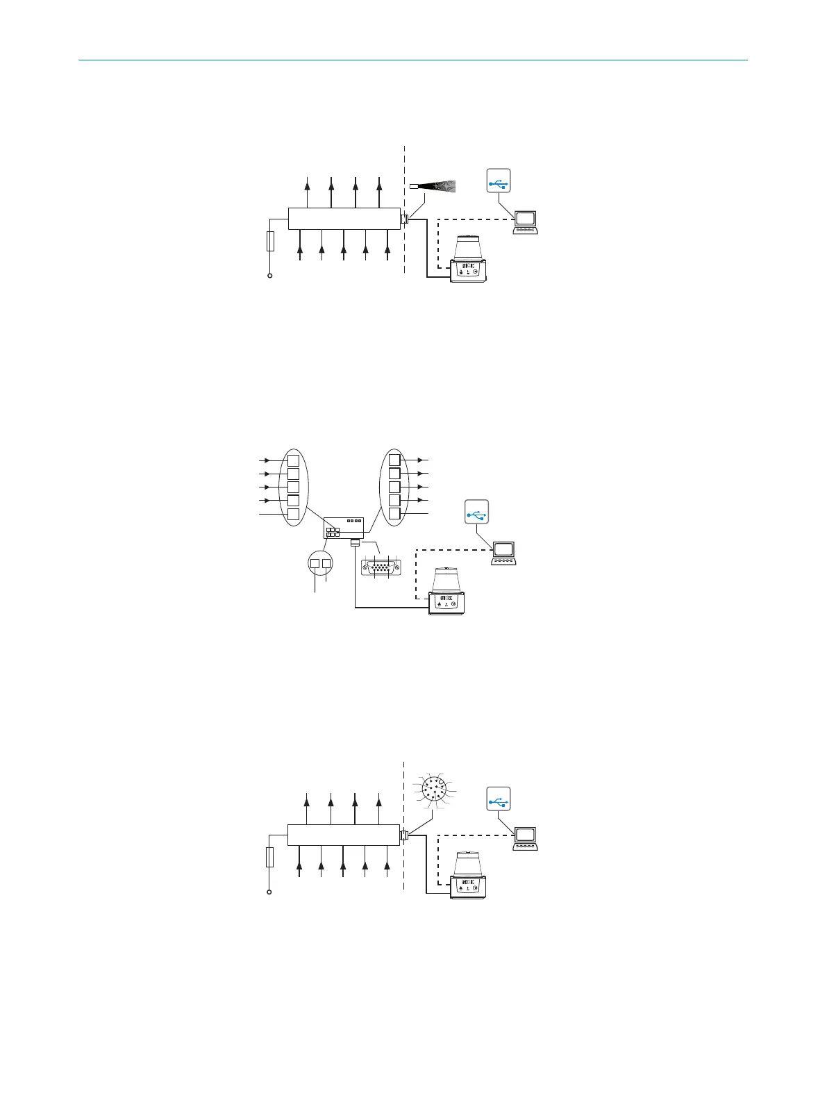
Figure 25: “Power//I/O” connection: Cable with M12 male connector, 12-pin, A-coded
1
Provided by customer
2
Device
3
Configuration, field monitoring or diagnostics
4
Connecting device
6 ELECTRICAL INSTALLATION
32
O P E R A T I N G I N S T R U C T I O N S | TiM3xx 8024851//2021-07-21 | SICK
Subject to change without notice