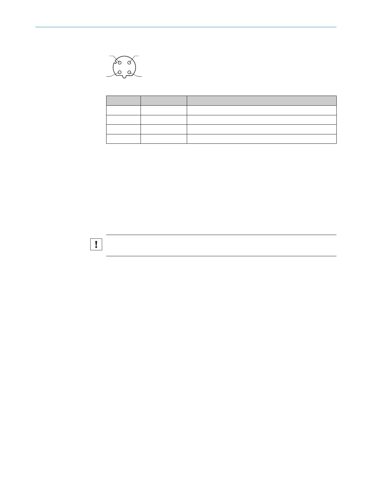
"Ethernet" connection (only TiMxxx-21xxxxx)
Table 10: Female connector, 4-pin, D-coded
Contact Labeling Description
1 TX+ Sender+
2 RX+ Receiver+
3 TX- Sender-
4 RX- Receiver-
6.4.4 USB interface (TiM35x / 36x only)
The Ethernet interface is recommended as a communication interface.
If using the USB interface, please note:
•
Use a high-speed UBS cable, maximum length of cable 3 m.
•
The connection may be interrupted due to ESD/EMC influences. If necessary:
Disconnect USB cable from the device, then reconnect it. Restart communication
via SOPAS ET software (“Online” button).
6.5 Connecting the device electrically
NOTICE
Observe the wiring instructions, see "Wiring instructions", page 33.
1. Ensure the voltage supply is not connected.
2. Connect the device according to the connection diagram, see "Connection dia‐
gram", page 33.
6.6
Wiring digital inputs / digital outputs
Digital inputs
The 4 switching digital inputs activate one of the 16 field sets in a binary combination
as an evaluation case.
The digital inputs are decoupled from the supply voltage of the device. They have a
common reference point (IN
GND
), meaning they are not decoupled from one another.
The structure and wiring principle of the digital inputs are shown below.
6 ELECTRICAL INSTALLATION
36
O P E R A T I N G I N S T R U C T I O N S | TiM3xx 8024851//2021-07-21 | SICK
Subject to change without notice