Pin Signal Function Wire colors of connecting
cable with flying leads
1
6 N.c. – Light blue
7 N.c. – Dark blue
8 IN 1 Digital input 1 (field set selection) Turquoise and light gray
9 IN 2 Digital input 2 (field set selection) Green
10 IN 3 Digital input 3 (field set selection) Gray
11 IN 4 Digital input 4 (field set selection) Pink
12 OUT 1 Digital output 1 (field breach) Brown
13 OUT 2 Digital output 2 (field breach) Orange
14 OUT 3 Digital output 3 (field breach) White
15 PNP: IN
GND
NPN: V
s
PNP: Common ground for all inputs
NPN: Common reference potential of
all inputs
White + black
– – Screen Metal
1
Example values when using the connecting cable part number 2043413. Signal assignment and wire
colors can vary when using other connecting cables.
6.4.3 TiMxxx-11xxxxx/
“Power/I/O” connection
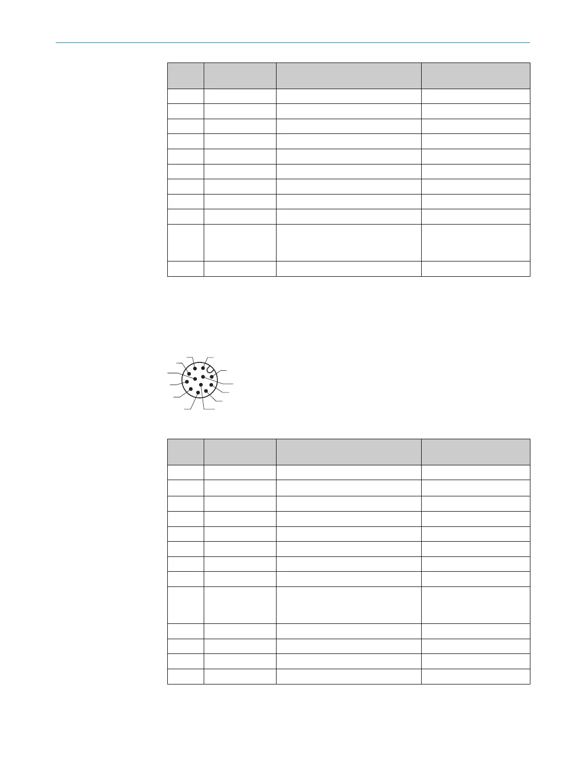
Table 9: Male connector, M12, 12-pin, A-coded
Pin Signal Function Wire colors of connecting
cable with flying leads
1
1 GND Ground Blue
2 V
S
Supply voltage Brown
3 IN 1 Digital input 1 (field set selection) Red
4 IN 2 Digital input 2 (field set selection) Green
5 OUT 1 Digital output 1 (field breach) Pink
6 OUT 2 Digital output 2 (field breach) Yellow
7 OUT 3 Digital output 3 (field breach) Black
8 OUT 4 Digital output 4 (index/error) Gray
9 PNP: IN
GND
NPN: V
s
PNP: Common ground for all inputs
NPN: Common reference potential of
all inputs
White
10 IN 3 Digital input 3 (field set selection) Violet
11 IN 4 Digital input 4 (field set selection) Gray + pink
12 – Reserved, do not wire this PIN! Red + blue
– – Screen –
1
Example values when using the connecting cables part numbers 6054974 (5 m), 6054973 (10 m),
6054972 (20 m). Signal assignment and wire colors can vary when using other connecting cables.
ELECTRICAL INSTALLATION 6
8024851//2021-07-21 | SICK O P E R A T I N G I N S T R U C T I O N S | TiM3xx
35
Subject to change without notice