9
Micro USB port, behind the black plaster cover (“Aux interface” connection for configura‐
tion with PC)
ß
Connection for power supply, digital inputs/outputs, 12-pin M12 female connector.
à
Marking for the position of the light emission level
á
Ethernet connection, 4-pin M12 female connector
â
Area in which no reflective surfaces are permitted when the device is mounted
ã
Bearing marking to support alignment (90° axis)
ä
270° aperture angle (visual range)
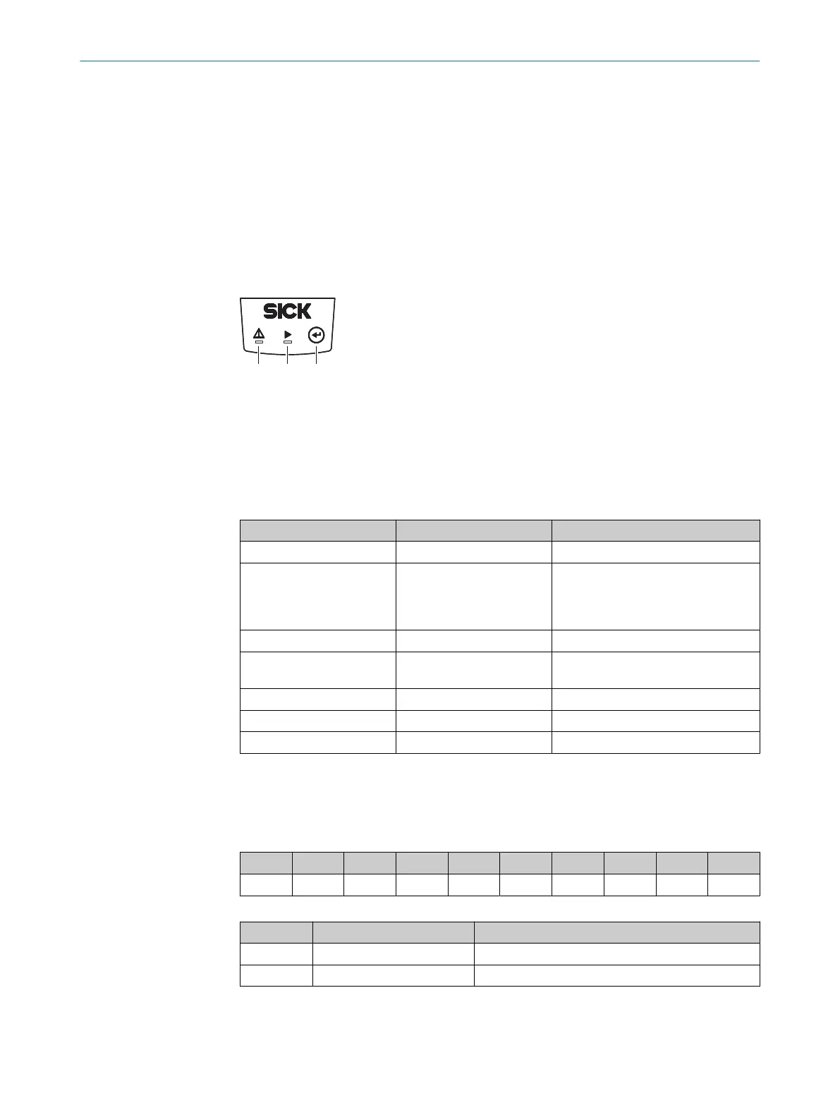
3.3 Display and operating elements
Figure 3: Display and operating elements
1
Red LED (status indicator)
2
Green LED (status indicator)
3
Teach-in pushbutton
Status indicators
LED (red) LED (green) Description
-
O
Device ready/monitoring mode
O O
Field breach (if there are lots of field
breaches in a short space of time,
the red LED lighting up might look
like flashing)
-
Ö
Teach-in: start
O O
Teach-in: End of advance warning
phase, 60 seconds Teach-in level
-
Ö
Teach-in: End of teach-in phase
Ö
- Fault
- - Device without supply voltage
O = illuminated; Ö = flashing
3.4 Type code
The devices of the product family are arranged according to the following type code:
TIM x y z ‒ aa bb c dd
1 2 3 4 5 6 7 8 9
Table 3: Type code
Position Description Characteristic
1 Device name TIM: Short range 2D-LiDAR sensor
2 Device type 3: Field evaluation
PRODUCT DESCRIPTION 3
8024851//2021-07-21 | SICK O P E R A T I N G I N S T R U C T I O N S | TiM3xx
13
Subject to change without notice